


Falcon 36 Operation Manual Operation
GBC Pro-Tech 1997 October
3-5
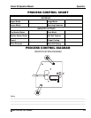
3URFHVV&RQWURO&KDUWV
Process control charts allow you to record the way
you thread film through the machine's rolls and
idlers (called webbing) and the control settings for
each product and process. Process control charts are
an excellent tool for training new operators. They
provide a "road map" for correct machine setup and
operation.
This section contains a blank process control chart
and diagram for the Falcon 36 as well as completed
charts for the basic operations of the laminator.
GBC Pro-Tech laminators respond in a very
accurate and repeatable manner. The charts provide
a way to set up each time, every time for repeatable
performance by assuring that all controls are set to
optimum.
The process control charts should be kept in this
manual or in a book close to the laminator. Use the
machine to encapsulate the popular charts so they
can withstand food and coffee spills and so they are
always available for ready reference.
⇒
NOTE
When trying new products and processes, remember
that GBC Pro-Tech's customer service
representatives are only a phone call away. In North
America, call 1-800-236-8843.
The completed process control charts included in
this section are based on Falcon Film, Falcon Board,
and typical prints.
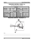
0RXQWLQJDQG/DPLQDWLQJ2QH
3DVV
1. Adjust the machine settings as shown in process
chart 3-2.
WARNING
Do not operate the laminator without the
infeed table installed on the machine.
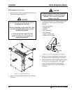
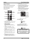
2. Load the film onto the upper unwind assembly.
3. Insert Orca board, adhesive side down, in
between the rolls. Lower them until they contact
with the board. Turn the crank another 1/4 of a
turn. Set the machine to reverse and remove the
board by activating the motor. Do not adjust the
roll crank after setting the nip. Reset the
machine to forward operation.
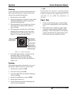
4. Web the film by wrapping it around the upper
film idler and draping it over the upper main
roll. Have about six inches laying on the infeed
table.
5. With a leader board of the same thickness as the
mounting board, (make sure the leader board is
also as wide as the film being used) press the
footswitch and insert the leader board into the
nip, square to the rolls. Thin input from the film
should lay flat on the upper main roll. Stop
feeding once the back edge of the board is one
inch from the nip.
6. Lay the image onto the adhesive side of the
Falcon Board. Tacking the image down with a
tacking iron at this point is sometimes helpful.
7. Push the Falcon board and image up against the
leader board and press the footswitch. Be sure to
maintain paper tension throughout this
procedure.
8. Once the board is through the nip and it no
longer continues to feed, disengage the
footswitch and raise the main roll. With a knife,
cut the laminate on the infeed side. Pull the
mounted image through the pull rolls. Do this
quickly so as to eliminate the possibility of
getting adhesive on the machine.
⇒
NOTE
You can run more than one image and board during
a run of this process. Feed one board after another,
until complete. Make sure that the edge of the board
being fed into the nip is pushed up against the rear
edge of the board already in the nip area.