10
TEST PROCEDURES
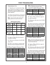
4.4 Apply a 100Hz, 500mVrms signal to
the input of the 802C.
4.5 Reference a dB meter to the 302 AMP
output jacks (while in the Bi-Amp mode).
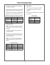
4.6 Refer to the frequency response table
below and verify the response of the unit.
6. Noise Test
6.1 All noise measurements are ANSI
A-weighted true rms, with the inputs
shorted.
6.2 Refer to the table below for the proper
noise levels.
5. Distortion Test
Note: Total harmonic distortion must be
measured in all modes to assure proper
operation.
5.1 Apply a 750Hz, 5Vrms signal to the
input of the 802C.
5.2 Refer to the table below for the distor-
tion specification for the corresponding
mode being tested.
Note: For the Bi-Amp 302 reading the
input signal should be a 100Hz, 5Vrms
signal.
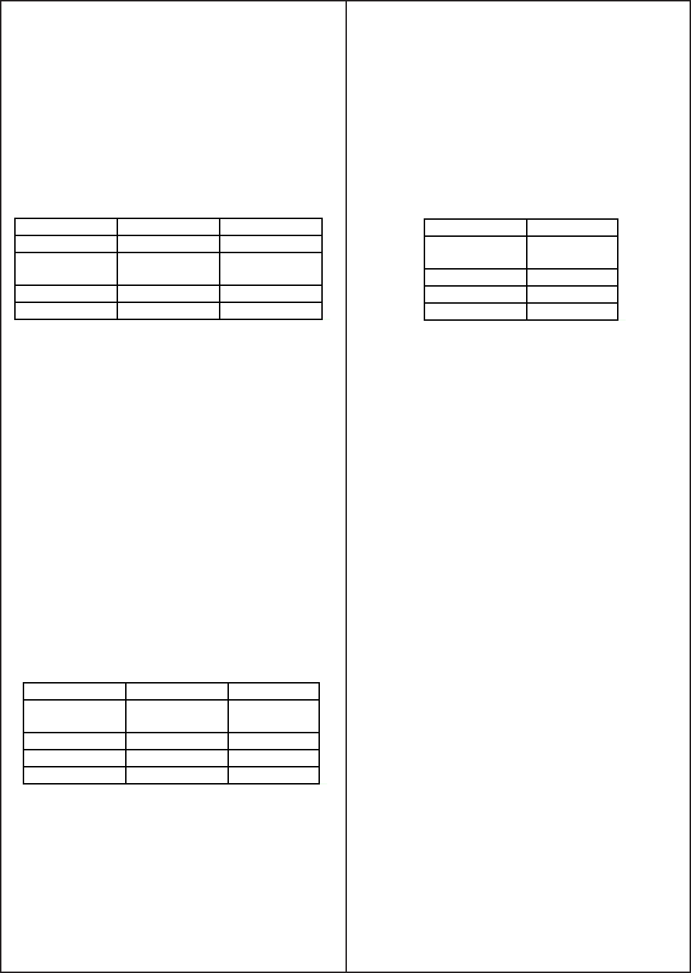
Frequency Output Tolerance
55Hz +3.7dB ± 1.5dB
100Hz 0dB
(reference)
-
230Hz -8.3dB ± 1.5dB
750Hz -25.8dB ± 2.5dB
302 Bi-Amp Frequency Response Table
Output Frequency. Distortion
802 Full
Range
750Hz <0.1%
302 Passive 750Hz <0.1%
802 Bi-Amp 750Hz <0.1%
302 Bi-Amp 100Hz <0.1%
Distortion Table
Noise Table
Output Noise
802 Full
Range
<20uV
302 Passive <20uV
802 Bi-Amp <20uV
302 Bi-Amp <10uV


