


43
APPENDIX
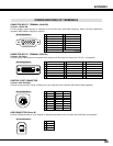
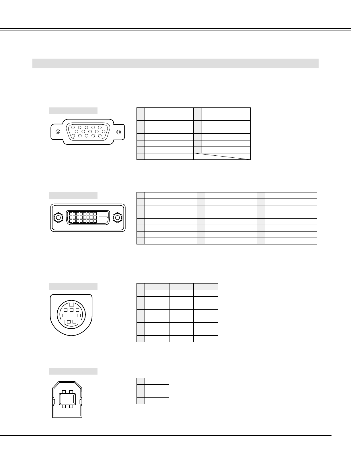
CONFIGURATIONS OF TERMINALS
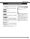
COMPUTER INPUT-1 TERMINAL (ANALOG)
Terminal : HDB15-PIN
Connect display output terminal of computer to this terminal with VGA Cable (supplied). When connecting Macintosh
computer, MAC Adapter (supplied) is required.
5
1
2
34
10
9 678
15
14
13
11
12
Red Input
Ground (Horiz.sync.)
Green Input
Sense 2
Blue Input
Ground (Red)
Ground (Green)
Ground (Blue)
1
5
2
4
3
6
7
8
+5V Power
Horiz. sync.
Ground (Vert.sync.)
DDC Data
Sense 0
Vert. sync.
DDC Clock
9
13
10
12
11
14
15
Pin Configuration
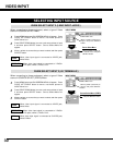
Terminal : Mini DIN 8-PIN
Connect control port (PS/2, Serial or ADB port) on your computer to this connector with Control Cable (supplied).
1
2
3
4
5
8 7 6
Pin Configuration
CONTROL PORT CONNECTOR
-----
CLK
DATA
GND
-----
-----
GND
-----
R X D
-----
-----
GND
RTS / CTS
T X D
GND
GND
-----
ADB
-----
GND
-----
-----
-----
GND
PS/2 Serial
ADB
1
2
3
4
5
6
7
8
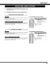
COMPUTER INPUT-1 TERMINAL (DIGITAL)
Terminal : DVI 24-pin
Connect display output terminal of computer to this terminal with DVI cable (for Single Link T.M.D.S. / not supplied).
1
9
17
2
10
18
3
11
19
4
12
20
5
13
21
6
14
22
7
15
23
8
16
24
T.M.D.S. Data2–
No Connect
T.M.D.S. Data2+
No Connect
T.M.D.S. Data2 Shield
DDC Clock
DDC Data
No Connect
1
5
2
4
3
6
7
8
Pin Configuration
T.M.D.S. Data1–
No Connect
T.M.D.S. Data1+
No Connect
T.M.D.S. Data1 Shield
+5V Power
Ground (for +5V)
Hot Plug Detect
9
13
10
12
11
14
15
16
T.M.D.S. Data0–
No Connect
T.M.D.S. Data0+
No Connect
T.M.D.S. Data0 Shield
T.M.D.S. Clock Shield
T.M.D.S. Clock+
T.M.D.S. Clock–
17
21
18
20
19
22
23
24
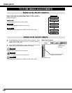
Vcc
- Data
+ Data
Ground
1
2
3
4
USB CONNECTOR (Series B)
Pin Configuration
Connect USB port terminal on your computer or peripheral equipment to this connector with USB Cable (not supplied).
2
34
1