


7
2
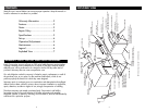
CONTENTS
Read this user’s manual before use to ensure proper operation. Keep the manual on
hand for reference in case there is a problem.
Warranty Information .....................2
Features .........................................3
Notes ............................................3
Repair Policy ..................................3
Specifications .................................3
Set-up ............................................4
Operation/Adjustments ...................5
Maintenance ..................................6
Legend ...........................................6
Exploded View ...............................7
Brady Corporation warrants all parts on DSP series label dispensers against defects
in design, materials and workmanship for a period of 180 days. Labor to replace
defective parts will be performed at no charge for the first 90 days after date of
purchase. Warranty does not cover transportation costs.
Our sole obligation under this warranty is limited to repair, replacement or credit of
the purchase price, at our option, for the machines listed above, which do not
perform properly the function for which they were designed.
Warranty repair is contingent upon our examination and determination that alleged
defects have not been caused by misuse, abuse, improper installation or application,
repair, alteration, accident or neglect in use, storage, transportation or handling.
The above warranty and remedy constitutes Brady Corporation’s sole liability
hereunder and are in lieu and exclusive of all other warranties and remedies
expressed, implied, or statutory, including, but not limited to, those of merchantability
and fitness for a particular purpose.
WARRANTY POLICY FOR DSP SERIES LABEL DISPENSERS
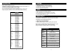
6-MOTOR
6A-Motor/Main Plate screw(2ea)
2-REEL HOLDER ARM
2A-Arm/Main Plate screw(1ea)
1-COVER
1A-Cover/Base screw(4ea)
20-POWER INLET
18-POWER SWITCH
3-REEL HANGER BAR
3A-Bar/Arm screw(1ea)
7-SQUARE LOCK ROD
8-TAKEUP HUB
8A-Hub/Motor set screw(1ea)
10-GUIDE ROD
10A-Rod/Main Plate screw(1ea)
11-BRUSH HOLDER
11A-Holder/Main Plate "T" screw(1ea)
11B-Holder/Brush set screw(2ea)
12-HOLD DOWN BRUSH
13-STRIP PLATE
13A-Strip Plate/Main Plate screw(2ea)
13B-Teflon Tape
15-PHOTOSENSOR BRACKET
15A-Bracket/Main Plate "T" screw(2ea)
15B-Bracket/Sensor screw(2ea)
14-PHOTOSENSOR
16-MAIN PLATE
5-REEL GUIDE(2ea)
21-DAISY CHAIN INLET
4-3" SPOOL(2ea)
17-BASE
17A-Base/Main Plate screw-side(1ea)
17B-Base/Main Plate screw-bottom(2ea)
19-CIRCUIT BOARD
19A-Board/Base screw(4ea)
19B-Board/Base nut(4ea)
19C-Board/Base spacer(4ea)
22-TRANSFORMER
9-SHAFT COLLAR
9A-"T" adjustment screw(1ea)
NOTE: Drawing not to scale – for reference only.
EXPLODED VIEW