Ref Qty Part# Description
AA 4 015-0045 Floor Glides
BB 16 030-0325 1/4-20 x 1/2” Truss Screws
CC 12 030-0207 1/4-20 Flanged Hex Nuts
DD 4 030-0313-901 Machine Rest Cups
EE 4 030-0272 1/4-20 x 1/2” Carriage Bolts
FF 4 030-0274 Lock Washers
GG 4 030-0006 1/4-20 Wing Nuts
1 018-0034 13” Ground Wire
HARDWARE LIST
STEP 1
AA
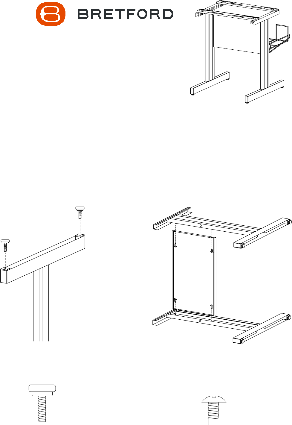
Twist on the floor glides (AA) onto
the bottom of both pedestals.
Lay one pedestal on a flat surface with holes facing
upward. Position modesty panel on pedestal panel and
attach with screws (BB). Position other pedestal on
modesty panel and attach with screws. Stand unit upright.
STEP 2
BB
PARTS LIST
Qty Part# Description
2 010-1627 Machine Rests
4 010-1629 Extender Brackets
1 010-1630 Modesty Panel
1 014-0166 Wire Basket
1 022-1324 Right Pedestal Assembly
1 022-1325 Left Pedestal Assembly
TOOLS REQUIRED
Phillips Screwdriver
Adjustable Wrench
Assembly Instructions
PRINTER STAND
UNI1
