


6
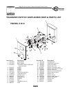
Briggs & Stratton Power Products Automatic Transfer Switch
Installation and Owner’s Manual
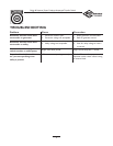
Mounting Guidelines
The Automatic Transfer Switch is enclosed in a NEMA Type
3R enclosure suitable for indoor/outdoor use. Guidelines for
mounting the Automatic Transfer Switch include:
• Install the switch on a firm, sturdy supporting structure.
• The switch must be installed with minimum NEMA 3R
hardware for conduit connections.
• To prevent switch contact distortion, level and plumb the
enclosure.This can be done by placing washers between
the switch enclosure and the mounting surface.
• NEVER install the switch where any corrosive substance
might drip onto the enclosure.
• Protect the switch at all times against excessive moisture,
dust, dirt, lint, construction grit and corrosive vapors.
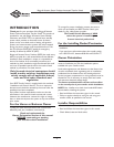
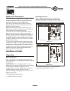
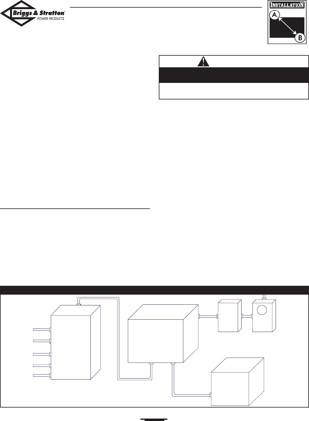
A typical installation of the Automatic Power Transfer
Switch is depicted in Figure 2. It is best if it is mounted
near the utility meter, either inside or outside. Discuss
layout suggestions/changes with the owner before beginning
the system installation process.
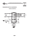
Power Wiring Interconnections
All wiring must be the proper size, properly supported and
protected by conduit.
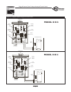
Complete the following connections between the transfer
switch, main distribution panel, utility power and generator
(Figure 3, on next page).
1. Ensure utility power is turned OFF. Connect utility
power supply leads to transfer switch terminals
marked “UTILITY CONNECTION”.
2. Connect utility neutral to the transfer switch
“NEUTRAL” terminal.
3. Connect main distribution panel power leads to transfer
switch terminals marked “LOAD CONNECTION”.
4. Connect main distribution panel neutral lead to
transfer switch “NEUTRAL” terminal.
5. Connect generator power supply leads from the
generator’s control panel to transfer switch terminals
marked “GENERATOR CONNECTION”.
6. Connect generator Neutral from the control panel to
the transfer switch “NEUTRAL” terminal.
7. Connect generator “GND” from the control panel to
the transfer switch “GND” terminal.
8. Connect main distribution panel “GND” to the
transfer switch “GND” terminal.
9. Connect generator utility 240 VAC terminals to
transfer switch utility 240 VAC terminals.
10. Terminal strip on control module in transfer switch has
four connections for customer use.There are two sets
of “Normally Closed” contacts available.They will be
activated when generator power is required.These can
be used for supervisory control of large connected
loads on generator, for example, disconnecting air
conditioner, water heater, etc. or an alarm source.
11. Tighten all wire connections/fasteners to proper torque.
• Failure to follow above warning could cause damage and/or
malfunction of equipment.
Low voltage wire cannot be installed in same conduit
as power voltage wiring.
CAUTION
Figure 2 — A Typical Transfer Switch Mounting
Main
Breaker
Panel
Transfer Switch
Generator
Service
Disconnect
Watt-
Hourmeter