


14 BRIGGSandSTRATTON.COM
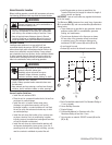
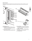
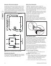
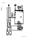
Generator AC Connection System
A single-phase, three-wire AC connection system is used in
the home generator. The stator assembly consists of a pair
of stationary windings with two leads brought out of each
winding. The junction of leads 22 and 33 forms the neutral
lead, as shown schematically and as wiring diagram below. A
complete schematic and wiring diagram can be found in the
separate illustrated parts list manual.
NOTE: Neutral is not bonded to ground at generator.
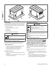
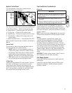
Grounding the Generator
Ground the home generator per applicable codes, standards,
and regulations. The generator GND lug is located inside the
control panel door under the circuit breaker cover.
Utility Circuit Connection
“240V Utility” leads must be routed in conduit. The
“240V Utility” leads deliver power to the generator’s circuit
board, optional battery warmer and optional oil warmer. This
power also charges the battery. When power on these leads
is lost, the generator will start.
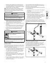
Using provided 2 pole connector plug and installer-supplied
minimum 300V, 14 AWG copper wire, connect each control
circuit terminal in the generator to the two-amp fuse
terminals in the automatic transfer switch.
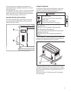
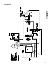
Transfer Switch Communication
Using #18 AWG twisted pair conductors, no greater than
200 ft in length, connect Tx Rx and Tx Rx Ground from the
generator control panel to the GND and T/R on the transfer
switch control board.
Fault Detection System
The generator may have to run for long periods of time with
no operator present. For that reason, the system is equipped
with sensors that automatically shut down the generator
in the event of potentially damaging conditions, such as
low oil pressure, high temperature, over speed, and other
conditions. Refer to Fault Detection System in Maintenance
for more detailed information.
The owner will use the remote LED indicator to observe the
status of the home generator system. Consult with the owner
for a convenient location. Locate the electrical box in an
area visible by the home owner such as near a garage door
opener or security control panel.
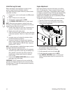
To install the remote LED indicator:
1. Push the LED through the mounting plate from the
front until it snaps in place.
IMPORTANT: The LED is polarity sensitive.
2. Using provided 10 pole connector and installer-supplied
minimum 18AWG wire, connect the remote LED to the
generator control board +LED and GND connection.
Use wire nuts to attach wire to LED leads.
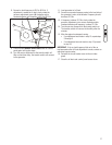
3. Attach mounting plate to installer-supplied electrical box.
Generator
Transfer
Switch