9
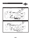
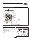
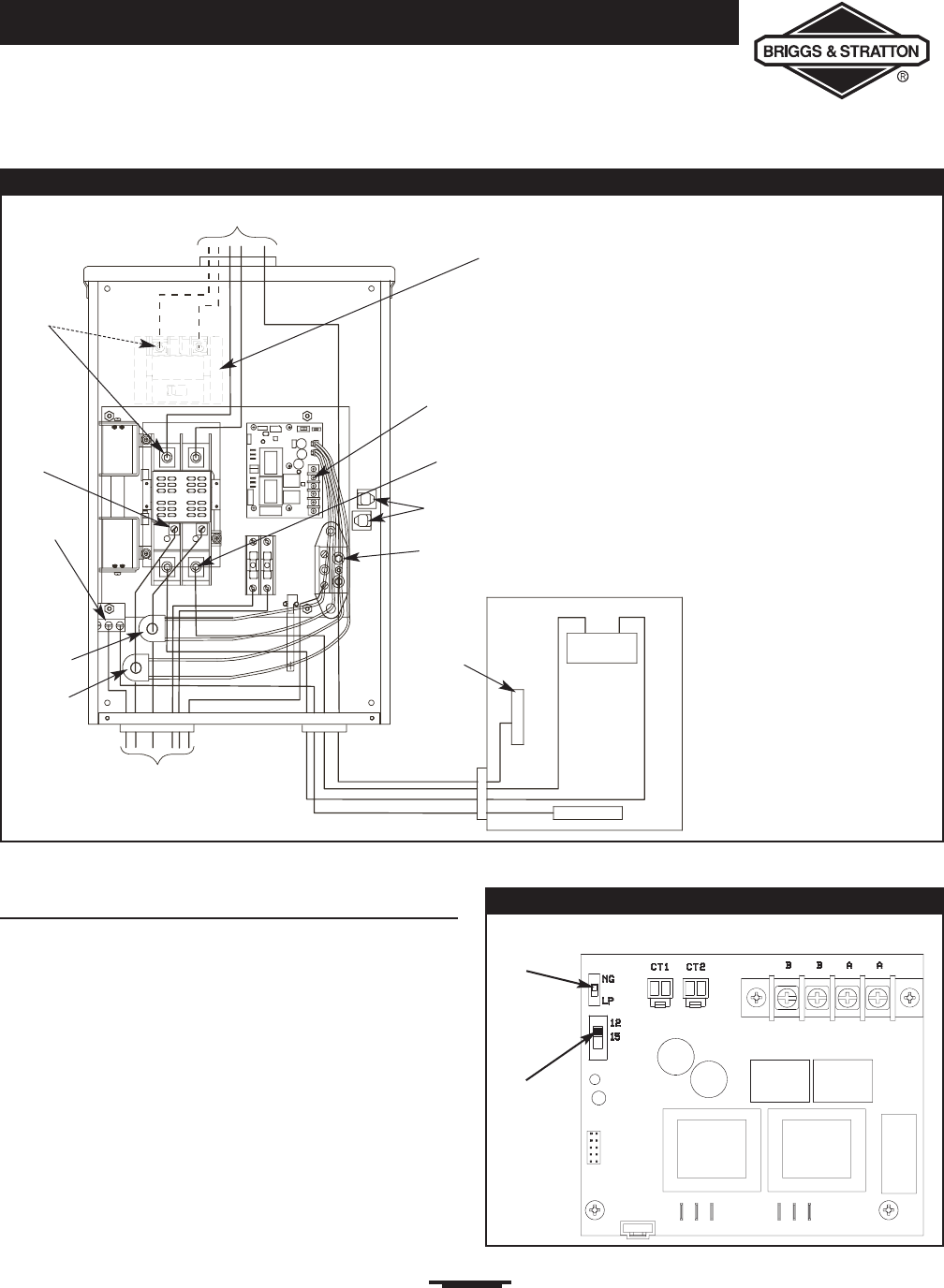
Figure 4 — A Typical Installation Diagram for Transfer Switch
Main
Main Distribution Panel
Ground Bus
Neutral
Bus
To Generator
Neutral
Terminal
To Utility Power
Supervisory
Contacts
Load
Connection
Ground
Terminal
Generator
Connection
Utility
Connection
INSTALLATION
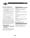
System Setup
You must perform the following before operating the
system:
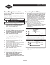
• Place the 2 position sliding switch on the control module
in the NG or LP position (Figure 7), whichever is
appropriate for your system.
• Place the 3 position sliding switch on the control module
to match the KW rating of the Home Standby Generator
set (Figure 7).
Figure 7 — Control Module
2 Position
Switch
3 Position
Switch
NOTE: Models 071010 and 071011 have a utility disconnect
circuit breaker built into the transfer switch enclosure.
Wireways
CT 1
CT 2


