9
Specifications
UL® 1008 Listed Transfer Switch
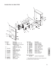
Model 071018
Maximum Load Current . . . . . . . . . . . . . . . . . . . . .100 Amps
Rated AC Voltage . . . . . . . . . . . . . . . . . . . . . . . . . .250 Volts
Poles . . . . . . . . . . . . . . . . . . . . . . . . . . . . . . . . . . . . . . . . . .2
Frequency . . . . . . . . . . . . . . . . . . . . . . . . . . . . . . . .50/60 Hz
Fault Current Rating . . . .22,000 RMS Symmetrical Amperes
Supervisory Contacts Rating:
A-A Terminals . . . . . . . . . . . . . . . . . . . . . . . . . .24 Volt AC
B-B Terminals . . . . . . . . . .1 Amp, 125 Volt AC, Pilot Duty
Weight . . . . . . . . . . . . . . . . . . . . . . . . . . . . . . . . . . . .21 lbs.
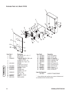
Model 071019
Maximum Load Current . . . . . . . . . . . . . . . . . . . . .200 Amps
Rated AC Voltage . . . . . . . . . . . . . . . . . . . . . . . . . .250 Volts
Poles . . . . . . . . . . . . . . . . . . . . . . . . . . . . . . . . . . . . . . . . . .2
Frequency . . . . . . . . . . . . . . . . . . . . . . . . . . . . . . . .50/60 Hz
Fault Current Rating . . . .25,000 RMS Symmetrical Amperes
Supervisory Contacts Rating:
A-A Terminals . . . . . . . . . . . . . . . . . . . . . . . . . .24 Volt AC
B-B Terminals . . . . . . . . . .1 Amp, 125 Volt AC, Pilot Duty
Weight . . . . . . . . . . . . . . . . . . . . . . . . . . . . . . . . . . . .34 lbs.
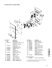
Model 071020
Maximum Load Current . . . . . . . . . . . . . . . . . . . . .100 Amps
Rated AC Voltage . . . . . . . . . . . . . . . . . . . . . . . . . .250 Volts
Poles . . . . . . . . . . . . . . . . . . . . . . . . . . . . . . . . . . . . . . . . . .2
Frequency . . . . . . . . . . . . . . . . . . . . . . . . . . . . . . . .50/60 Hz
Fault Current Rating . . . .22,000 RMS Symmetrical Amperes
Supervisory Contacts Rating:
A-A Terminals . . . . . . . . . . . . . . . . . . . . . . . . . .24 Volt AC
B-B Terminals . . . . . . . . . .1 Amp, 125 Volt AC, Pilot Duty
Weight . . . . . . . . . . . . . . . . . . . . . . . . . . . . . . . . . . . .32 lbs.
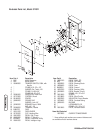
Model 071021
Maximum Load Current . . . . . . . . . . . . . . . . . . . . .200 Amps
Rated AC Voltage . . . . . . . . . . . . . . . . . . . . . . . . . .250 Volts
Poles . . . . . . . . . . . . . . . . . . . . . . . . . . . . . . . . . . . . . . . . . .2
Frequency . . . . . . . . . . . . . . . . . . . . . . . . . . . . . . . .50/60 Hz
Fault Current Rating . . . .25,000 RMS Symmetrical Amperes
Supervisory Contacts Rating:
A-A Terminals . . . . . . . . . . . . . . . . . . . . . . . . . .24 Volt AC
B-B Terminals . . . . . . . . . .1 Amp, 125 Volt AC, Pilot Duty
Weight . . . . . . . . . . . . . . . . . . . . . . . . . . . . . . . . . . . .44 lbs.
Maintenance
The transfer switch is designed to be maintenance free under
normal usage. However, inspection and maintenance checks
should be made on a regular basis. Maintenance will consist
mainly of keeping the transfer switch clean.
Visual inspections should be done at least once a month.
Access to transfer switch must not be obstructed. Keep
3 feet (1 m) clearance around transfer switch. Check for an
accumulation of dirt, moisture and/or corrosion on and
around the enclosure, loose parts/hardware, cracks and/or
discoloration to insulation, and damaged or discolored
components.
Exercise the transfer switch at least once every three months
as described in section Testing the Automatic Transfer
Switch unless a power outage occurs and home generator
system has gone through an automatic sequence. Allow
generator to run for at least 30 minutes.
Contact a licensed electrical professional to inspect and clean
the inside of your transfer switch at least once a year.


