


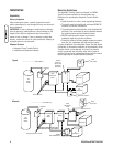
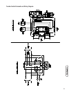


Power Wiring Interconnections
All wiring must be the proper size, properly supported and
protected by conduit.
Complete the following connections between the transfer
switch, main distribution panel, utility power and generator.
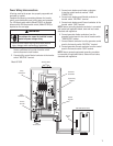
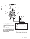
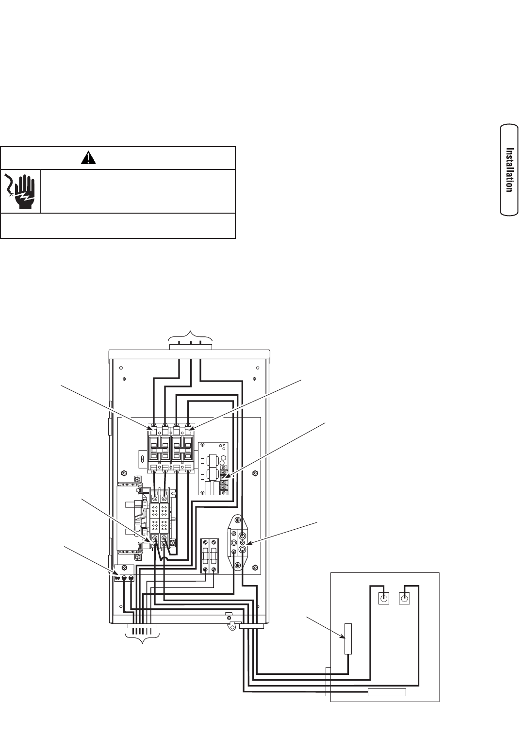
The 100 Amp transfer switch (Model 071022) is depicted
below and the 200 Amp transfer switch (Model 071023) is
depicted on the next page.
WARNING
Low voltage wire cannot be installed in same
conduit as power voltage wiring.
Failure to follow above warning could cause personal
injury, damage and/or malfunction of equipment.
•
1. Ensure utility power is turned OFF. Connect utility
Service conductors to line side of transfer switch
service disconnect circuit breaker.
2. Connect utility service Neutral conductor to the transfer
switch “NEUTRAL” terminal.
3. Connect main breaker panel feeder conductors
to transfer switch terminals marked “LOAD
CONNECTION”.
4. Connect main breaker panel Neutral conductor to
transfer switch “NEUTRAL” terminal.
5. Connect main breaker panel Ground conductor to the
transfer switch “GND” terminal.
NOTE: Assure grounding electrode conductor is connected
and bonded per applicable federal, state and local codes,
standards and regulations.
6. Connect generator feeder conductors from the
generator control panel to line side of transfer switch
“GENERATOR” breaker.
7. Connect Neutral conductor from the generator control
panel to the transfer switch “NEUTRAL” terminal.
8. Connect generator Ground conductor from the control
panel to the transfer switch “GND” terminal.
NOTE: Assure generator equipment grounding conductor
is connected per applicable federal, state and local codes,
standards and regulations.
7
Ground Bus
Main
To Generator
Neutral
Terminal
Supervisory
Contacts
To Utility Meter
Generator
Connection
Utility
Connection
Main Distribution Panel
Ground
Terminal
Neutral
Bus
Load
Connection
Model 071022