


4424 Blade Server SAN I/O Module Hardware Reference Manual 5
53-0000571-01
Hardware Description
1
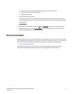
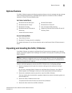
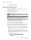
The nonport (SAN I/O Module status) LEDs, shown as item 3 of Figure 1, display SAN I/O
Module-level information as shown in Figure 2.
FIGURE 2 Other Status LEDs
1 SAN I/O Module status LED
2 Power status LED
3 Server Management LED
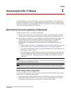
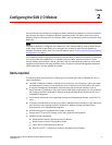
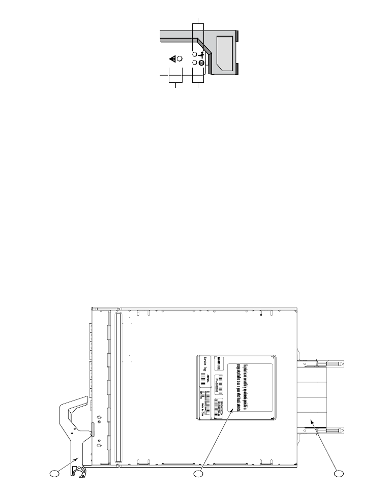
Nonport side
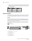
The nonport side of the SAN I/O Module (shown in Figure 3) is seated into the enclosure. You do
not need to line up the SAN I/O Module as it will seat correctly when the insertion arm is closed.
When the SAN I/O Module is inserted, the backplane connectors activate a connection port,
allowing the SAN I/O Module to be configured in the Blade Server Enclosure.
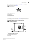
FIGURE 3 Nonport Side, Viewed from Top
1. I/O module handle. Lifting the handle’s release latch opens the handle to install and remove
the module from the Blade Server Enclosure.
2. Product label including serial number.
3. Connectors
1 2
3
1
2
3