


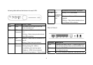
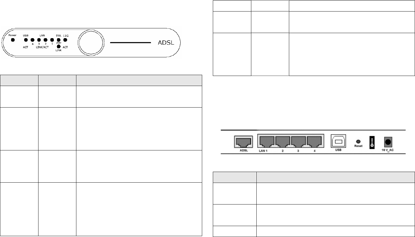
following table defines the behavior for each LED:
LED Represents Activity / Status
Power Power The Power LED will light up when the
device is powered on.
USB USB
Connection
- Steady on – USB is connected to a host
PC.
- Blinking – Data is being transferred over
the USB connection.
1, 2, 3, 4 LAN
Connection
Steady on - when there is a connection to
the unit.
Blinking – Data is being transferred.
DSL DSL
Connection
- Off - ADSL link is not connected.
- Blinking During Off - ADSL is
handshaking and receiving signal.
- Steady on - ADSL link is connected.
- Blinking During steady on - Data is being
transferred over the ADSL connection.
PPP Link PPP
Connection
Blinking – PPP is connected.
11G Wireless
LAN
- Steady on – Wireless LAN access point is
enabled.
- Blinking – Data is being transferred over
the Wireless LAN connection.
Back Panel
Connector Description
ADSL Connect one end of the RJ-11 cable to the ADSL
port and connect the other end to the ADSL line.
LAN 1-4 Accepts a RJ-45 Ethernet cable for connecting up
to 4 network devices.
USB For USB connection (optional), connect the USB
4