


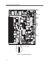
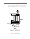
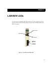

LANVIEW LEDs
4-2
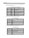
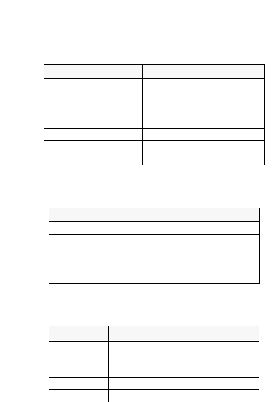
The functions of the two System Status LEDs, System Management Bus (SMB)
and the CPU, are listed in Table 4-1.
The functions of the INB transmit LED are listed in Table 4-2.
The functions of the INB receive LED are listed in Table 4-3.
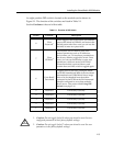
Table 4-1. System Status (SMB and CPU) LEDs
LED Color State Description
Green Functional Fully operational
Yellow Testing Power-up testing
Yellow (Flashing) Crippled Not fully operational (e.g., one bad port)
Yellow/Green Booting Blinks yellow and green while booting
Red Reset Normal power-up reset
Red (Flashing) Failed Fatal error has occurred
Off Power off Module powered off
Table 4-2. INB Transmit LED
LED Color State
Green (Flashing) Data activity
Yellow (Flashing) Port in standby state
Red (Flashing) Collision
Red Fault
Off No activity, Port disabled
Table 4-3. INB Receive LED
LED Color State
Green (Flashing) Link, Port disabled
Green Link, Port enabled, No activity
Yellow (Flashing) Link, Port enabled, Activity
Red Fault
Off No Link