


Chapter 2: Installation
2-8 HSIM-G01/G09 User’s Guide
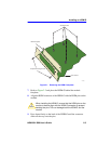
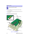
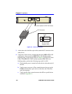
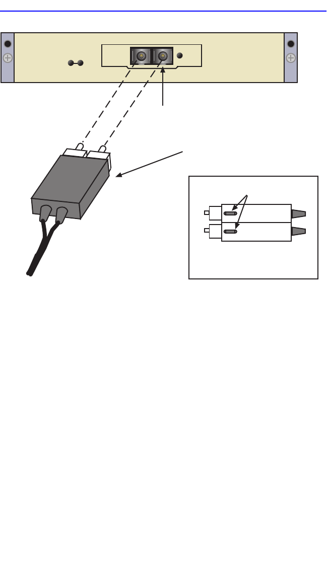
Figure 2-4 Fiber Connections
3. At the other end of the fiber optic cable, attach the SC connector to the
other device.
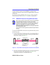
4. Verify that a link exists by checking that the link (LNK) LED is ON
(solid green), the port receive (RX) LED is ON (flashing amber,
blinking green, or solid green). Refer to Chapter 3 for the layout of the
LEDs. If the RX LED is OFF and the transmit (TX) LED is not
blinking amber, perform the following steps until it is ON:
a. Check that the power is turned on for the device at the other end of
the link.
b. Verify proper crossover of fiber strands between the port on the
HSIM-G and the fiber optic device at the other end of the fiber
optic link segment.
c. Verify that the fiber connection meets the dB loss specifications
outlined in Appendix A.
SC Connector
Key Latch (bottom of SC Connector)
(bottom view)
keys
SC Connector
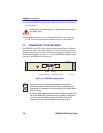
HSIM-G
LNKSX