


2-5
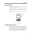
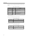
Local Management Console
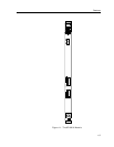
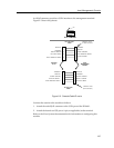
An RJ-45 connector provides a CON interface to the management terminal.
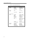
Figure 2-3 shows the pinouts.
Figure 2-3. Console Cable Pinouts
Connect the console to the module as follows:
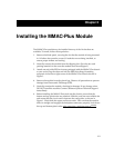
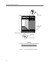
1. Attach the male RJ-45 connector to the CON port of the 9F106-01.
2. Attach the female end (25-pin or 9-pin, as applicable) to the terminal.
Refer to the Cisco Systems documentation for information on configuring this
module.
Pin 1
RJ-45 COM PORT
CLEAR TO SEND
2
3
5
7
RECEIVE
TRANSMIT
SIGNAL GROUND
RJ-45 TO 25 PIN
CABLE
FEMALE - 25 Pin
"D" Shell Connector
20 DATA TERMINAL READY
4
1
5
2
6
TRANSMIT
RECEIVE
DATA SET READY
DATA TERMINAL READY
SIGNAL GROUND
COM PORT
RJ-45
LOCAL
MANAGEMENT
CONSOLE
RECEIVE
TRANSMIT
SIGNAL GROUND
RJ-45 TO 9 PIN
CABLE
FEMALE - DB-9
(9-Pin Connector)
3
2
5
8
DATA SET READY
1
4
5
2
6
TRANSMIT
RECEIVE
SIGNAL GROUND
7
DATA TERMINAL READY
CLEAR TO SEND
READY TO SEND