6 MPS14 User Guide
The MPS14
The slimline MPS14 power supply uses switch mode technology to generate the DC voltages required by the
console. It will operate from a wide range of ac mains input voltages. Full protection and thermally controlled fan
cooling ensures the power unit will operate consistently. The MPS14 also has a built in combiner for connection to
a second supply for backup.
Installation
Free standing
The MPS14 can be operated as a freestanding unit without requiring any special cooling arrangement, but should
not be accidentally or deliberately covered in any way. Always stand the unit on a firm flat surface well away from
any soft furnishings or carpet.
Rack mounting
The MPS14 is designed as a 19 inch rack mount unit and will occupy 2U (3.5 inches) of rack space. A pair of M4
threaded holes on each side at the rear of the chassis are provided for fixing brackets for supporting the rear of
the unit.
An important consideration when rack-mounting the unit is the need for natural convection of airflow over the
whole unit.
Good ventilation below the unit, in the floor or back of the rack, will ensure a path for continuous airflow.
Other equipment in the rack which is known not to produce a significant amount of heat should be mounted below
the unit. Equipment which also relies on good airflow within the rack (i.e. most power amplifiers and other power
supplies) should be given due consideration and some space should be provided between such units and
between the MPS14 unit. Forced convection, by means of a fan-tray, may be desirable in this situation.
Location
As with any power supply that contains switch mode technology, it is preferable to provide a degree of physical
isolation of the unit from other equipment, particularly that which carries low level audio signals, to avoid any
possible interference pick-up. For this reason the unit is provided with a long (2.9m) output cable to enable it to be
positioned away from the mixing console. For the same reason, when rack-mounting it is preferable to avoid
locating the unit next to signal processing equipment.
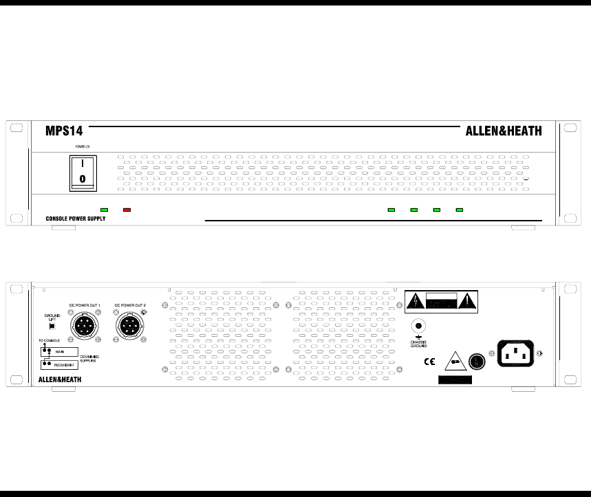
CONSOLE POWER SUPPLY
MPS14
PIN 1 = + 12V @ 4A
PIN 4 = A GND
PIN 3 = A GND
PIN 6 = + 48V @ 500mA
PIN 5 = D GND
FUSE
435W MAX100V - 230V.AC 47-63 Hz ~
ADVANCED TECHNOLOGY / HIGH POWER DELI VERY / AUTO COMBINI NG
+17V -17V + 12V + 48VON P R OT E C T
CAUTI ON: FOR CONTI NUED PROTECTION AGAI NST RISK OF FIRE REPLACE FUSE
ATTENTI ON: REMPL ACER LE FUSIBL E AVEC UN DES MEMES CARACTERIST IQUES.
WITH SAME TYPE AND RATI NG. DISCONNECT SUPPLY BEFORE CHANGING FUSE.
DO NOT OPEN. NO USER SERVICEABLE PARTS I NSIDE.
DO NOT OBSTRUCT VENTILATI ON OPENINGS.
THIS APPARATUS MUST BE EARTHED BY THE POWER CORD.
COUPER L'ALI MENTATION AVANT DE CHANGER LE FUSIBLE.
WARNING: TO REDUCE THE RISK OF ELECTRIC SHOCK
DO NOT EXPOSE THIS APPARA TUS TO RAIN OR MOISTURE.
T5A250V
T
MAINS INPUT
A DIVISION OF HARMAN INTERNATI ONAL I NDUSTRIES LTD
MADE IN ENGLANDS/ No
AVIS: RISQUE DE CHOC ELECTRIQUE - N E PAS OUVRIR.
CAUTION
PIN 2 = + 17V @ 6.5A
PIN 7 = -17V @ 6.5A


