


INSTALLING THE NB20E OR NB25E BRIDGE
3-4
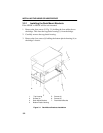
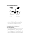
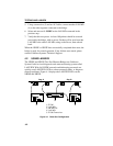
Figure 3-3 Installation
2. Attach an AUI cable (2, 8) no more than 50 meters in length to each of
the transceivers that you connected to each network segment.
3. Connect the AUI cable from the transceiver to the AUI port (4, 5)
located on the back panel of the NB20E or NB25E bridge.
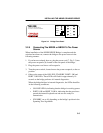
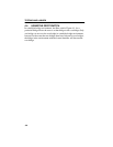
3.2.4 Setting The Mode Switches
Before connecting the bridge to the power supply, set the Forward
Broadcast and Root switches to the appropriate On (
|
) or
Off (
O
) position as defined below:
• If you want the bridge to pass Broadcast messages between segments,
set the FORWARD BROADCAST switch (Fig. 3-4) to the On (
|
)
position.
• If you want this bridge to receive priority over all other bridges on the
network, set the ROOT switch (Fig. 3-4) to the On (
|
) position. Only
ONE bridge on the network should have the ROOT switch enabled.
9
1
2
3456
7
810
1. ST-500 Transceiver 6. Power Receptacle
2. AUI Cable 7. Power Cord
3. Bridge 8. AUI Cable
4. AUI Port 2 9. ST-500 Transceiver
5. AUI Port 1 10. RS232 Port (NB25E only)