


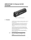
SDM-CD16AC 16 Channel AC/DC Controller
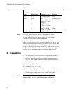
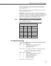
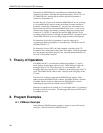
TABLE 1. Datalogger to SDM-CD16AC Connections
Connection
Order
SDM-CD16AC
Datalogger (see note)
Function
First 12 V 12 V on datalogger or Power
external supply
Second Gnd Gnd Common ground
C1 SDM-C1 (CR3000,
CR5000) or C1 (other
dataloggers)
Data
C2 SDM-C2 (CR3000,
CR5000) or C2 (other
dataloggers)
Clock
C3 SDM-C3 (CR3000,
CR5000) or C3 (other
dataloggers)
Enable
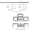
On a CR7, SDMs connect to the ports at the upper right corner
of the 700X Control Module. On a CR9000X, SDMs connect to
the ports on the CR9032 CPU Module, and on a CR9000, SDMs
connect to the ports on the CR9080 PAM Module.
NOTE
If the 21X power supply is used to power the SDM-CD16AC, all low level
analog measurements (thermocouples, pyranometers, thermopiles, etc.) must
be made differentially. This is a result of slight ground potentials created
along the 21X analog terminal strip when the 12 V supply is used to power
peripherals. This limitation reduces the number of available analog input
channels and may mandate an external supply for the SDM-CD16AC.
4. Installation
• The SDM-CD16AC must be installed in an enclosure that provides a
pollution degree 2 environment (normally, only nonconductive pollution.
However, a temporary conductivity caused by condensation may be
expected). All Campbell Scientific enclosures meet this requirement.
• Use copper conductors only.
• Wire Range: 30 − 14 AWG
• Tightening Torque: 5 − 7 in./lb.
• Use minimum 60/75 degree C wire.
• Input power must be connected to a class 2 supply only. All Campbell
Scientific power supplies meet the class 2 supply requirements.
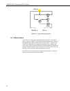
The order in which connections are made is critical.
Always connect 12 V first, followed by ground, then Control
Ports.
CAUTION
4