


SDM-CVO4 4-Channel Current/Voltage Output Module
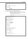
; then set the value to –3000
13: Z=F (P30)
1: -3000 F
2: 00 Exponent of 10
3: 5 -- Z Loc [ ScldOut_1 ]
14: End (P95)
15: End (P95)
; Now update the SDM-CVO4 with the information
; for the four channels
16: SDM-AO4 (P103)
1: 4 Reps
2: 30 SDM Address
3: 5 Loc [ ScldOut_1 ]
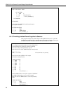
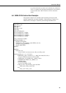
6.2.3 Providing Isolated Power Supplies to Sensors
SDM-CVO4 to 10 V to provide
t
; {CR10X}
This program example sets all the outputs of the
isolated power supplies to four separate sensors. The program includes code to pu
the SDM-CVO4 into standby mode after the measurements are made.
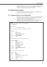
; An example program which show use of the SDM-CVO4
; as an isolated power supply for 4 sensors requiring
; 10 V drive and producing 0-100 mV signals.
; This shows how to set the SDM-CVO4 into standby mode.
*Table 1 Program
01: 60 Execution Interval (seconds)
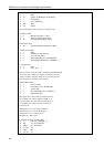
; S ixed val 5000 = 10 V output tore a f ue of
; in the four scaling locations
1: Bulk Load (P65)
1: 5000 F
2: 5000 F
3: 5000 F
4: 5000 F
5: 0.0 F
6: 0.0 F
7: 0.0 F
8: 0.0 F
9: 1 Loc [ Scale_1 ]
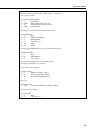
; T t V puts to 10,000 mV ell he SDM-C O4 to set all four out
; The SDM-CVO4 address is zero in this example.
; This will cause the SDM-CVO4 to come out of standby
; mode.
2: SDM-AO4 (P103)
1: 4 Reps
2: 00 SDM Address
3: 1 Loc [ Scale_1 ]
18