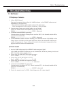
1.3 No Picture
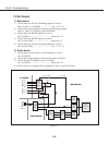
1) AV board
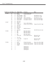
1. Check that the Vcc-voltages(+5V, -5V) are applied to AV circuits.
Pins 47-50 of K10A, Pins 47-54 of K10B ..............5V
Pins 39-42 of K10B..............................................-5V
Check IC1001, IC1002 and IC1021.
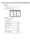
2. Check that the following input signals are observed correctly.
2) Main board
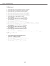
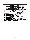
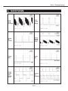
1. Check the signals at following test points.
• Video signal at TP208, TP218
• V-sync signal at TP7224
• H-sync signal at TP7223
2. Check that the PC/AV switching signal is correct.
Pin 16 of IC5201 .................................................AV: H, PC: L
Pin 5 of IC5282....................................................AV: H, PC: L
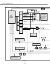
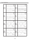
3. Check that the RGB signals are observed at following test points.
TP211, TP221R, TP2211R ....................................R-signal
TP212, TP221G, TP2221G....................................G-signal
TP213, TP221B, TP2231B ....................................B-signal
4. Check that the signals are observed at following test points.
TPDHS, TP3322 ...................................................V-Sync,
TPDVS, TP3321 ...................................................H-Sync
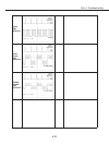
5. Check that the RGB drive signals are observed at fllowing test point.
TP501 ..................................................................R-signal
TP531 ..................................................................G-signal
TP561 ..................................................................B-signal
6. Check that the S/H signals are observed at following test points.
TP1501, TP501R, TP502R ....................................R-signal
TP1531, TP503G, TP504G....................................G-signal
TP1561, TP505B, TP506B ....................................B-signal
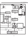
7. Check that the PSIG signals are observed at test points TP1401 and TP1451.
Part 4: Troubleshooting
4-7
SIGNAL K10A-pin No. K50A-pin No.
V-Sync 17-18 17-18
H-Sync 15-16 15-16
B 11-12 11-12
G 9-10 9-10
R 7-8 7-8
Video 33-34 33-34
S-C 29-30 29-30
S-Y 25-26 25-26


