


4
TO SHUT UNIT OFF
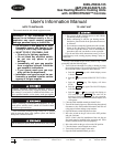
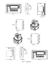
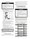
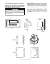
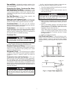
See Fig. 1 for location of gas valve(s). Refer to Fig. 3 while
proceeding with the following steps.
1. Turn off the unit demand for cooling or heating by using
the scrolling marquee. The scrolling marquee is located in
the control box at the compressor end of the unit.
a. Push the key unit a blank display screen
is shown.
b. Push the key until the SERVICE TEST LED is
lit.
c. Push the key. The display will show
STOP.
d. Push the key again. The NO/YES display
will flash.
e. Push the or key to toggle the display to
YES and then push . The unit will be
locked off from heating, cooling or any operation.
The controls will still function and the display will
still operate.
2. Close the field-installed manual gas shutoff valve.
3. Turn off the electrical power to the unit using the optional
disconnect or the field-installed disconnect and lock off
using proper lockout and tag-out procedures.
4. Open the burner section hinged access door.
5. Move the switch on the gas valves to the OFF position
and wait 5 minutes before doing any service in the section
or on the piping.
6. Close the burner section hinged access door.
7. If unit is being shut down because of a malfunction, call
your dealer as soon as possible.
If unit is being shut down because the heating season has
ended, restore electrical power to the unit and reset the
scrolling marquee to Run mode to ensure operation of the
cooling system during the cooling season.
Do not use this unit if any part has been under water. Imme-
diately call a qualified service technician to inspect the unit and
to replace any part of the control system and gas control that
has been under water.
MAINTAINING YOUR UNIT
All maintenance should be handled by skilled, experienced
personnel. Your dealer can help you establish a standard
procedure.
For your safety, keep the gas heating area clear and free of
combustible materials, gasoline, and other flammable liquids
and vapors.
To ensure proper functioning of the unit, flow of combus-
tion and ventilating air must not be obstructed from reaching
the gas heating area. Clearance of at least 4 ft on all sides is
required.
ROUTINE MAINTENANCE AND CARE
FOR THE EQUIPMENT OWNER
Before proceeding with those things you might want to
maintain yourself, please carefully consider the following:
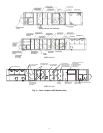
Air Filters — Air filters should be checked at least every
3 or 4 weeks and changed or cleaned whenever they become
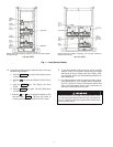
dirty. Table 1 indicates the correct filter size for your unit. Open
the hinged filter access door to replace or inspect the filters. All
units have filter tracks into which the filters slide. Remove the
filters by pulling outward from the track. See Fig. 4 for filter
access door location. Note the direction of flow arrows on the
filter frame.
If you have difficulty in locating your air filter in the return-
air duct system, or if you have questions concerning proper
filter maintenance, contact your dealer for instructions.
Table 1 — Indoor-Air Filter Data*
*See base unit Installation Instructions if field-supplied or optional
factory-supplied filters are used. When replacing filters, always use
the same type and size originally supplied.
Do not turn off the electrical power to unit without first
turning off the gas supply.
Never attempt to manually light the main burners on a unit
with a match, lighter, or any other flame.
If the electric sparking device fails to light the main burn-
ers, refer to the following shut off procedure, then call your
dealer as soon as possible.
Failure to follow these procedures can result in serious fire
or personal injury.
IMPORTANT: Should overheating occur or the gas supply
fail to shut off, shut off the manual gas valve to the unit
before shutting off the electrical supply.
ESCAPE
ENTER
ENTER
ENTER
1. TURN OFF GAS SUPPLY FIRST AND THEN
ELECTRICAL POWER TO YOUR UNIT BEFORE
SERVICING OR PERFORMING MAINTENANCE.
2. Do not turn off electrical power to this unit without
first turning off the gas supply.
3. When opening access doors or performing mainte-
nance functions inside your unit, be aware of sharp
sheet metal parts and screws. Although special care
has been taken to reduce sharp edges to a minimum,
be extremely careful when handling parts or reaching
into the unit.
Failure to follow these procedures can result in serious fire
or personal injury.
UNIT SIZE
48Z
FILTER TYPE
QUANTITY...Size
(in.)
030-050
Disposable Fiberglass
(Standard) or Medium Effi-
ciency 30% Pleated (Optional)
8...20 x 25 x 2,
8...20 x 20 x 2
90% Bag (Optional) with High-
Velocity Pre-Filters
6...20 x 24 x 22,
6...20 x 20 x 22,
12...16 x 20 x 2,
3...20 x 24 x 2
055-070
Disposable Fiberglass
(Standard) or Medium Effi-
ciency 30% Pleated (Optional)
12...20 x 25 x 2,
12...20 x 25 x 2
90% Bag (Optional) with High-
Velocity Pre-Filters
6...24 x 20 x 22,
6...24 x 24 x 22,
6...20 x 24 x 2,
6...24 x 24 x 2
075
Disposable Fiberglass
(Standard) or Medium Effi-
ciency 30% Pleated (Optional)
12...20 x 25 x 2,
12...20 x 20 x 2
High Efficiency 65% Pleated
(Optional)
12...20 x 25 x 2,
12...20 x 20 x 2
090,105
Disposable Fiberglass
(Standard) or Medium Effi-
ciency 30% Pleated (Optional)
12...20 x 25 x 2,
12...20 x 20 x 2
High Efficiency 65% Pleated
(Optional)
12...20 x 25 x 2,
12...20 x 20 x 2