


2
1.2.2 Specifications
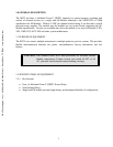
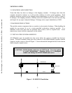
The M222 incorporates the standard 40-pin, 20x2 row connector interfaces to the carrier board
for power and data/control, but does not have the 24-pin optional connector for carrying user-
connections back onto the carrier board.
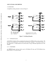
The user input/output is provided through a standard 44-pin D-subminiature female receptacle. A
mating connector kit can be ordered separately as AM111 (C&H Part Number 11029700-0001).
CONEC part number 302A10889X (or equivalent) is used on the assembly. The connector pin-
outs are shown in Appendix A.
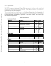
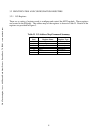
Table I. Specifications
MAXIMUM RATINGS
Parameter Condition Rating Units
Voltage Clean room Environment
(any terminal to any other terminal)
125
141
200
VDC
VAC rms
VAC peak
Non-Clean room Environment
(any terminal to any other terminal)
60
43
68
VDC
VAC rms
VAC peak
Current (non-inductive) Per Switch, DC
Per Switch, AC
Per Switch, AC
5
3.53
5
A
A rms
A peak
Power Per Switch, DC
Per Switch, AC
Per Module, DC
Per Module, AC
100
100
300
300
W
VA
W
VA
Thermal Offset < 20 µV typ
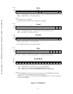
RESISTANCE
Parameter Condition Rating Units
Closed Channel End of Life < 2
Insulation Between any two points
≤40°C, ≤65% relative humidity
≤25°C, ≤40% relative humidity
10
8
10
8
typ
typ.
RELAYS
Parameter Condition Rating Units
Relay Life No load
Rated load
5 x 10
7
3.5 x 10
4
operations
operations
Time to open/close register programming 16 ms
AC
Parameter Condition Rating Units
Bandwidth -3dB 10 MHz typ
Channel-to-Channel Crosstalk <100KHz
<1MHz
<10MHz
<-80
<-60
<-40
dB
dB
dB
Closed Channel Capacitance Channel-to-Channel
Channel-to-Common
25
60
pF typ
pFtyp
C&H Technologies, Inc. <> 445 Round Rock West Drive <> Round Rock, TX 78681 <> www.chtech.com