


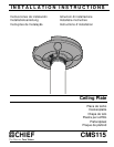


Installation Instructions CMS115
6
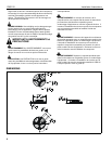
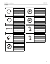
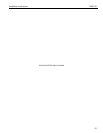
TOOLS REQUIRED FOR INSTALLATION
PARTS
1/4" (6.4mm)
9/16" (14.3mm)
5/16" x 1/8"
(7.9mm x 3.2mm)
B (1)
5/16" x 1/8"
(7.9mm x 3.2mm)
C (1)
A (1)
5/32"
(4.0mm)
D (1)
E (4)
5/16"
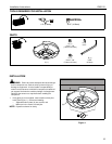
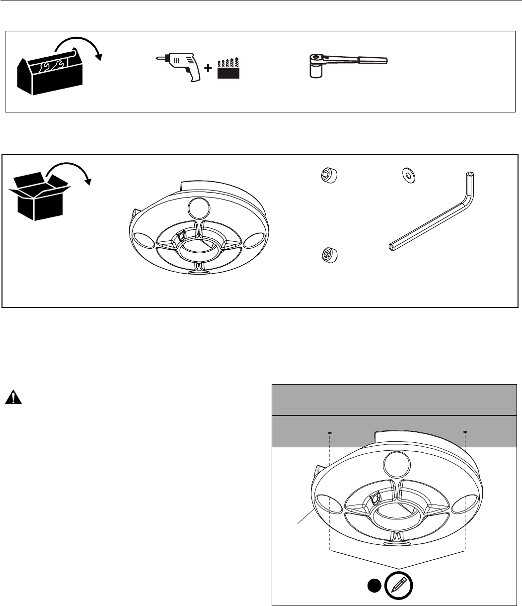
INSTALLATION
WARNING: Failure to provide adequate structural strength
for this component can result in serious personal injury or
damage to equipment! It is the installer’s responsibility to
make sure the structure to which this component is attached
can support five times the combined weight of all equipment.
Reinforce the structure as required before installing the
component.
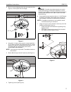
1. Using plate (A) as a template, mark locations of two pilot
holes (See Figure 1). Ensure the following:
• Opposite holes in plate (A) are marked, and
• Marks are in the center of wood joist.
NOTE: Drywall not shown for clarity.
Figure 1
1
x2
(A)