


S – VIDEO
USB
COMPUTER IN 2
DVI - I
MCI / WI
R – AUDIO IN – L
(MONO)
VIDEO
Pb / Cb – Pr / Cr
Y –
MONITOR OUT
COMPUTER IN 1
AUDIO IN 1
AUDIO IN 2
AUDIO OUT
RESET
CONTROL PORT
11
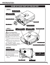
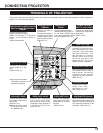
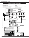
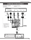
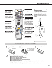
CONNECTING PROJECTOR
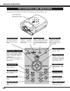
TERMINALS OF PROJECTOR
When controlling the computer
with Remote Control Unit of
this projector, connect the
mouse port of your personal
computer to this connector.
(Refer to P12.)
Connect the S-VIDEO
output from video
equipment to this
jack. (Refer to P13.)
Connect an audio output
(stereo) from computer to
these jacks.
(Refer to P12.)
CONTROL PORT CONNECTOR
COMPUTER AUDIO
INPUT (1 and 2) JACKS
Connect the audio output
from video equipment to
these jacks.
(Refer to P13.)
●When the audio output
is monaural, connect it
to L (MONO) jack.
AUDIO INPUT JACKS
VIDEO INPUT JACKS
S-VIDEO INPUT JACK
Connect the component
video output from video
equipment to connect the
component video outputs to
Y, Pb/Cb and Pr/Cr jacks.
(Refer to P13.)
COMPUTER INPUT 2 (DIGITAL/ANALOG)
Media Card Imager / Wireless Imager
TERMINAL
This projector has input and output terminals on its back for connecting computers and video equipment. Refer to figures on
pages 11 to 13 and connect properly.
Connect an external
audio amplifier to this
jack.
(Refer to P12, 13.)
This projector uses a micro
processor to control this unit,
and occasionally, this micro
processor may malfunction
and need to be reset. This
can be done by pressing
RESET button with a pen,
which will shut down and
restart the unit. Do not use
RESET function excessively.
RESET BUTTON
When controlling the computer
with Remote Control Unit of this
projector, connect USB port of
your personal computer to this
connector. (Refer to P12.)
USB CONNECTOR (Series B)
✽ Do not press this button.
This button is used for our
optional accessories.
Connect a monitor to
this terminal.
This terminal outputs a
computer input signal
(except Digital signal
input on DVI terminal).
(Refer to P12.)
MONITOR OUTPUT
TERMINAL
Connect computer output
(Digital / Analog DVI-I type),
Media Card Imager*, or Wireless
Imager* to this terminal. (Refer to
P12)
*optional accessories
VIDEO INPUT JACK
Connect the composite
video output from video
equipment to connect
this jack.
(Refer to P13.)
AUDIO OUTPUT JACK
Connect computer output
(Analog HDB 15-pin type) or
21-pin Scart (RGB) output
from video equipment to this
terminal. (Refer to P12, 13.)
COMPUTER INPUT 1
TERMINAL