


11
CONNECTING PROJECTOR
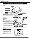
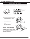
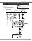
TERMINALS OF PROJECTOR
This projector applies various input/output terminals and 3 terminal slots for expansion to tune to diversity of signals from
computers and video equipment. 3-built-in Terminal Slots enable you to arrange desired combinations of input sources just
by changing Terminal Boards. For Terminal Boards, contact sales dealer where you purchased a projector.
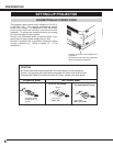
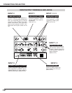
Screws
Guide
Socket
Plug
Figure shows HDB 15-PIN terminal (Optional parts).
Pull out terminal by holding handle.
Remove 2 Screws on terminal.
1
2
REPLACEMENT OF TERMINAL
Tighten screws to secure terminal.
Replace terminal. Insert terminal along Guide to fit Plug
into Socket.
3
4
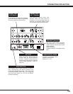
NOTES ON ORDERING OR USING
OPTIONAL INTERFACE BOARD
When ordering or using Optional Interface Board
(Terminal Board), contact your sales dealer. When con-
tacting the sales dealer, tell the Optional Control
Number (Op.cont.No.) in the menu that is located under
Language Select Menu. (See page 39.)
NOTE; When replacement of terminal board, MAIN
ON/OFF switch should be OFF position.
R/Pr G/Y B/Pb H/HV V
CONTROL PORT
INPUT 1
R/C JACK
USB
RESET
(MONO)
(MONO)
(MONO)
(MONO)
AUDIO
CONTROL PORT
S-VIDEO
VIDEO/Y
C
INPUT 2INPUT 3
AUDIO
AUDIO
SERIAL PORT IN
SERIAL PORT OUT
AUDIO OUT
R
L
R
L
R
R
L
L
ANALOG RGB
INPUT/OUTPUT
TERMINALS
HDB 15-PIN Terminal
5 BNC Terminal
AV Terminal
3 TERMINAL SLOTS (Factory set)