


Section 3: INSTALLATION
GS Series User Manual
020-000724-01 Rev. 1 (05-2014)
3-1
3. INSTALLATION
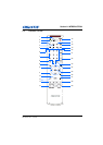
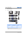
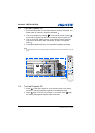
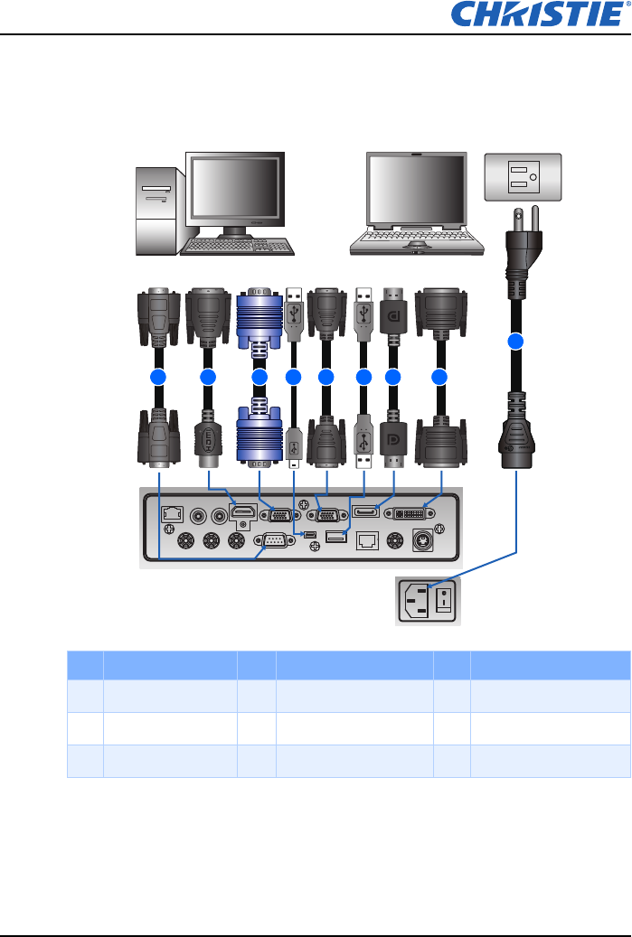
3.1 Connect to Computer
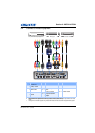
NOTE:
The diagram shows the cables/connectors that may be used to connect to various devices.
Due to the difference in applications for each country, the accessories required in some regions may be different from those
shown.
This diagram is for illustrative purposes only, and does NOT indicate that these accessories are supplied with the projector.
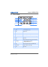
Ind. Connector Name Ind. Connector Name Ind. Connector Name
1 RS232 Cable 4 USB Type B Mini 7 Cable
2 HDMI Cable 5 VGA out Cable 8 DVI Cable
3 VGA in Cable 6 USB Type A Cable 9 Power Cord
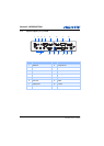
HDBaseT REMOTE
IN
GREEN/Y BLUE/PB RED/PR RS232 USB
MINI USB
ETHERNET CVBS S-VIDEO
REMOTE
OUT
HDMI VGA IN VGA OUT DISPLAY PORT DVI
Desktop
Laptop
1 2 3 4 5 6 7 8
9