


2-33
Cisco ONS 15454 DWDM Engineering and Planning Guide, Release 7.x
July 2006
Chapter 2 Cards Specifications
2.2.4 Optical Amplifiers
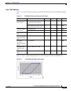
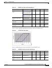
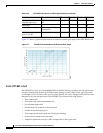
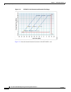
Figure 2-6 shows a graphical representation of the power mask for the OPT-BST card.
Figure 2-6 OPT-BST Card Power Mask
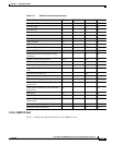
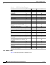
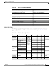
Table 2-24 defines the power and gain specifications for the OPT-BST-E card.
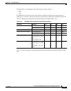
Table 2-23 OPT-BST Card Power and Gain Specification
Parameter Comment Min Typical Max Unit
Total input signal power
range
Full channel load; see
Figure 2-6 for detailed
Pin-Pout power mask
–3 — 12 dBm
Single channel; see
Figure 2-6 for detailed
Pin-Pout power mask
–21 — –6 dBm
Maximum output signal
power
Full channel load 17.0 — 17.5 dBm
Single channel –1.0 — –0.5 dBm
Maximum optical amplifier
signal gain
With tilt controlled at 0
dB
— — 20 dB
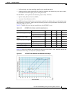
Gain range Figure 44 5 — 20 dB
Gain tilt error at target gain
tilt = 0 dB
— — — 0.5 dB
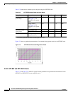
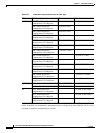
Table 2-24 OPT-BST-E Card Power and Gain Specifications
Parameter Comment Min Typical Max Unit
Total input signal power
range
Full channel load –26 — 12 dBm
Maximum output signal
power
Full channel load 20 — 20.5 dBm
Operative output power
range
— 2 — 20 dBm