5
e. Confirm that the router has power by checking that the PWR LED on the front panel is on.
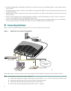
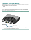
Step 2 To connect the router to your network, connect one end of an Ethernet cable to the Ethernet port (RJ-45), and connect
the other end of the cable to a port on the hub or switch, as shown in Figure 1.
Note The example provided in Figure 1 shows connectivity to a hub. The router’s Ethernet switch port can be
connected to another networked device, such as a switch or computer with a NIC. If you are connecting the
router’s switch port to another switch, use a crossover cable. If you are connecting a computer to the router’s
switch port, it will take about 30 seconds for connectivity to be established.
Step 3 To use Cisco Router and Security Device Manager (SDM) to configure your router, you must connect a PC to the first
Ethernet switch port on the 4ESW module. Connect one end of an Ethernet cable to the switch port labeled 1x, and
connect the other end to the Ethernet port on your PC.
Caution Always connect the Ethernet cable to an Ethernet port on the router. Accidentally connecting the cable to the wrong
port can damage your router.
Step 4 To connect the router to your service provider’s network, connect one end of an Ethernet cable to the 10/100
ETHERNET port (the yellow port); connect the other end of the cable to a network port on your service provider’s
broadband (xDSL or cable) modem equipment, as shown in Figure 1.
Caution Always connect the Ethernet cable to an Ethernet port on the router. Accidentally connecting the cable to the wrong
port can damage your router.
Step 5 (Optional) To make a backup connection to your service provider’s network, follow the instructions for your router
model below:
• The Cisco 1711 router supports a 56-kbps dial-up connection to your service provider’s network that can serve as
a backup connection to your service provider in the event that your primary connection goes down. To make a
backup dial-up connection, connect one end of a straight-through RJ-11 cable to the Analog Modem port on
WIC-1-AM module on the router, as shown in Figure 1, and connect the other end of the cable to your telephone
wall jack.
• The Cisco 1712 router supports an ISDN-BRI S/T connection to your service provider’s network that can serve as
a backup connection in the event that your primary connection go down. To make a backup ISDN connection,
connect one end of an RJ-45 ISDN cable to the ISDN-BRI S/T port on WIC-1B-S/T module on the router, as shown
in Figure 1; connect the other end of the cable to your ISDN wall jack.
Note To configure your router for a backup dial-up or ISDN connection, you must use the Cisco IOS command-line
interface (CLI). For more information, see the Cisco 1700 Series Router Software Configuration Guide.
5 Configuring the Router Using Cisco Router and Security Device Manager
Cisco Router and Security Device Manager (SDM) is a web-based configuration tool that allows you to configure LAN and
WAN interfaces, routing, Network Address Translation (NAT), firewalls, VPNs, and other features on your router. If SDM is
installed on your router, configure the router by following the instructions in the Cisco Router and Security Device Manager
(SDM) Quick Start Guide. If this document was not shipped with your router, you can obtain SDM and instructions for
installing it on your router from the following location:
http://www.cisco.com/pcgi-bin/tablebuild.pl/sdm
To obtain the SDM release notes, and other SDM documentation, go to http://www.cisco.com/go/sdm and click the Technical
Documentation link.


