


8
Cisco 1751 Voice-over-IP Quick Start Guide
78-11259-05
Installing WAN and Voice Interface Cards
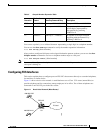
Note When the interface is configured as NT and is connecting to a TE device, the cable must have the transmit
and receive pins swapped (crossover cable). (See Table 3.)
Step 3 Connect the other end to the RJ-45 wall outlet.
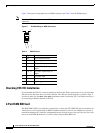
ISDN BRI Card LEDs
ISDN BRI voice interface cards have three LEDs, as listed in Table 4.
If you have additional cards to install, proceed to the appropriate sections in this manual. When you have
finished all installations, see the Cisco 1751 Router Software Configuration Guide available on the
Documentation CD-ROM.
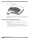
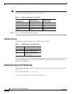
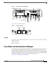
Determining Voice Port Numbering
Enter the show voice port command to identify the port numbers of voice interfaces installed in your
router:
Router# show voice port slot-number/port
Figure 8 on page 9 shows Cisco 1751 router slot numbering.
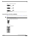
Table 3 Interface Pin Numbers and Functions
ISDN BRI NT/TE
NT Interface (use
straight-through cable)
TE Interface (use
crossover cable)
Pin 3/T+ Pin 3/R+ Pin 3/T+
Pin 4/R+ Pin 4/R+ Pin 4/R+
Pin 5/R- Pin 5/T- Pin 5/R-
Pin 6/T- Pin 6/R- Pin 6/T-
Table 4 ISDN BRI Voice Interface Card LEDs
LED Meaning
B1 Call active on B1 channel
B2 Call active on B2 channel
OK Interface is connected to an
ISDN network