


1-5
Cisco 1900 Series Hardware Installation
OL-19084-02
Chapter 1 Overview of the Router
Hardware Features
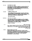
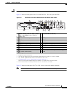
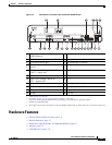
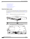
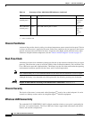
Figure 1-5 Back Panel of the Cisco 1941 and Cisco 1941W Router
Hardware Features
• Product Serial Number Location, page 1-6
• Built-In Interfaces, page 1-7
• Removable, Interchangeable, and Optional Modules, page 1-8
• Memory, page 1-9
• LED Indicators, page 1-10
1
USB ports—two USB 2.0 Type-A ports
(USB 0=Bottom)
2
L (Link)
3 GE 0/1 4 S (Speed)
5 RJ-45 serial console port 6 EN (Enable RJ-45 console)
7
USB serial port—USB 5-pin mini USB
Type-B
8
EN (Enable USB console)
9 HWIC slot 0 (EHWIC, HWIC, WIC, or
VWIC
1
)—single wide
2
1. VWIC support is for data only.
2. See Module Support on Cisco’s Integrated Services Routers Generation 2
http://cisco.com/en/US/prod/collateral/routers/ps10538/aag_c07_563807.pdf for supported modules.
10 ISM
3
or WLAN
3. Internal Service Module (ISM).
11 CF 0 12 CompactFlash 0
13 HWIC slot 1 (EHWIC, HWIC, or
WIC)—double wide
4
4. The double-wide slot can accommodate a single wide EHWIC, HWIC, WIC, or VWIC (data only), on the left side of the slot.
14 CF 1
15 CompactFlash 1 16 Kensington
TM
security slot
17 On/Off switch 18 Input power connection
19 AUX port 20 S (Speed)
21 GE 0/0 22 L (Link)
273452
L
CONSOLE
AUX
S
USB
1
G
E
0
/
0
0
EN
EN
CF 0
CF 1
ISM/WLAN
EHWIC 1
EHWIC 0
S
L
GE 0/1
DO NOT REMOVE DURING
NETWORKING OPERATION
DO NOT REMOVE DURING
NETWORKING OPERATION
Cisco 1900 Series
1516 38
7 6 5 4 2
2220
11
12
17 18 19 21
13
1
9
1014