Installing Cisco AC and DC Power Supplies in Cisco 2500 Series Routers 7
Replacing the Cover
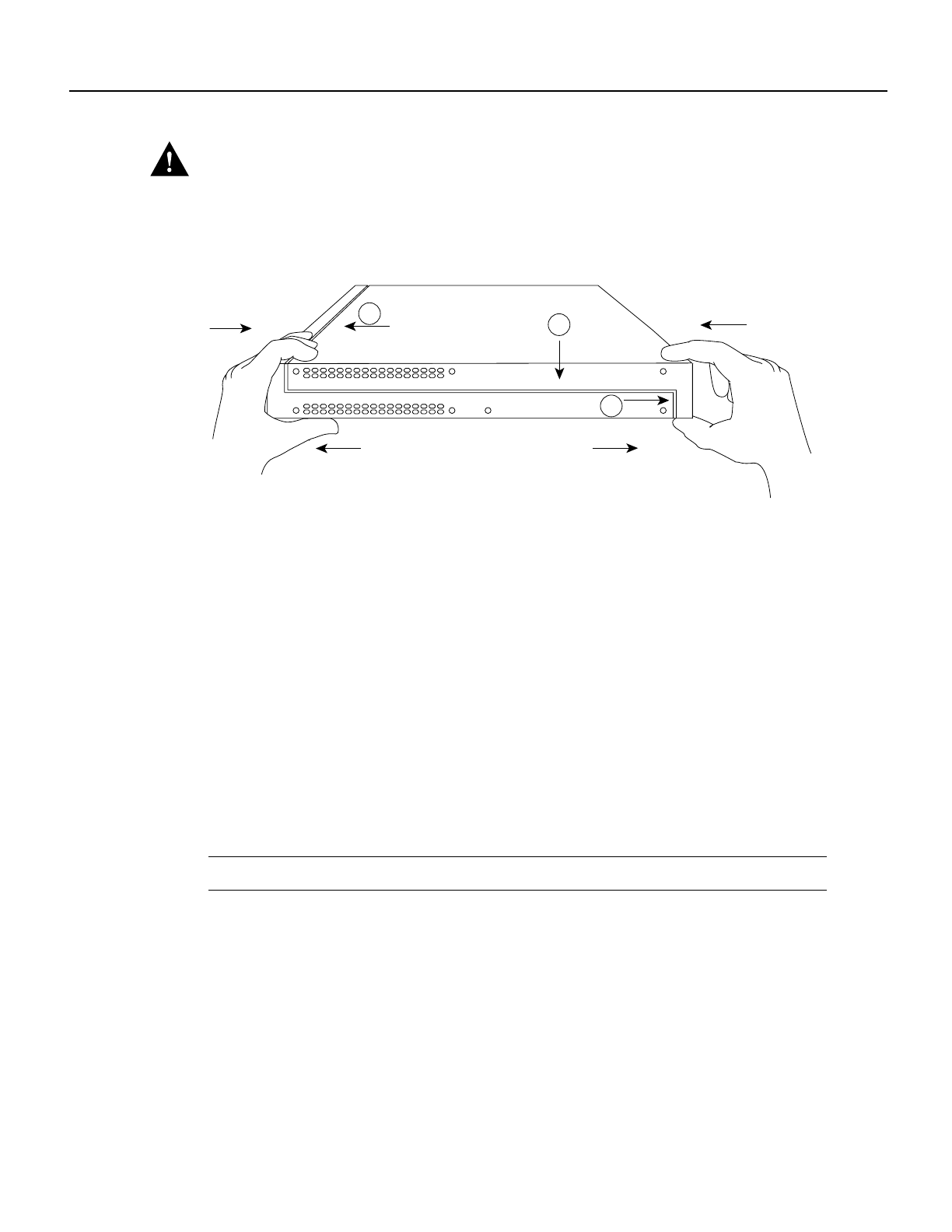
Caution To fit the two sections together, it may be necessary to work them together at one end and
then the other, working back and forth; however, use care to prevent bending the chassis edges. (To
see translated versions of this warning, refer to the Regulatory Compliance and Safety Information
document that accompanied the router.)
Figure 8 Replacing the Chassis Cover
Step 3
When the two sections fit together snugly, turn the chassis so that the bottom is facing up,
with the front panel toward you.
Step 4 Replace the cover screw. (See Figure 8.)
Step 5 Remove the protective cover from the back of the power requirements label.
Step 6 Carefully place the label directly over the silk screened power requirements information
on the rear panel of the system.
Step 7 Remove the protective cover from the back of the system designation label.
Step 8 Carefully place the label directly over the silk screened system designation information
on the rear panel of the system.
Step 9 Reinstall the chassis on the wall, rack, desktop, or table.
Step 10 Replace all cables.
Step 11 Remove your ESD-preventive wrist strap.
Note Ensure that the System OK LED is not covered by the system designation label.
This completes the procedure for installing AC and DC power supplies. If you have questions or
need assistance, see the section “Obtaining Service and Support.”
H3560
FrontRear
Left end
toward you
Top section
Bottom section
A
B
C


