


9
Installation Notes for Catalyst 3750-E, Catalyst 3560-E Switches and RPS 2300 Power Supply Modules
78-17570-01
Power Supply Module Installation
Grounding the Switch
Warning
This equipment must be grounded. Never defeat the ground conductor or operate the equipment in the
absence of a suitably installed ground conductor. Contact the appropriate electrical inspection
authority or an electrician if you are uncertain that suitable grounding is available.
Statement 1024
Warning
When installing or replacing the unit, the ground connection must always be made first and
disconnected last.
Statement 1046
Caution To make sure that the equipment is reliably connected to earth ground, follow the grounding procedure
instructions.
Follow these steps to install either a single-ground lug or a dual-ground lug on the switch. Make sure to
follow any grounding requirements at your site.
Step 1 Locate the ground lug screw and the lug ring in the switch accessory kit. For a dual-ground connection,
also locate the dual-ground adaptor and the dual-hole lug that ships with the DC power supply module.
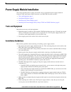
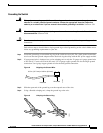
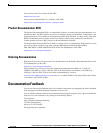
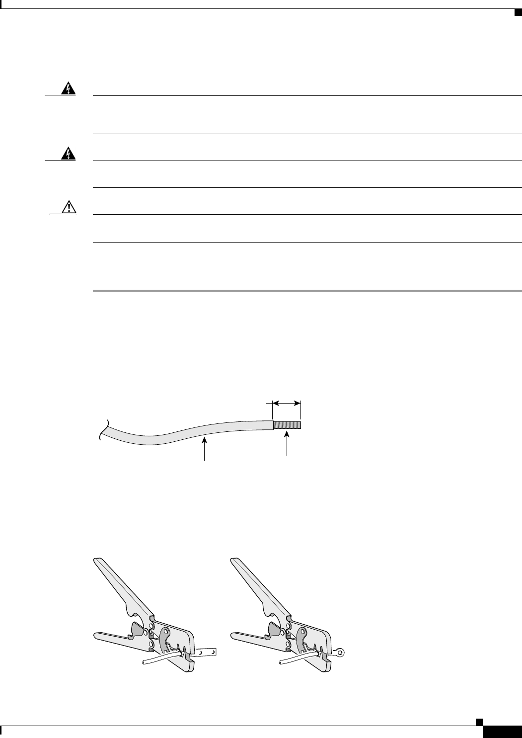
Step 2 If your ground wire is insulated, use a wire stripping tool to strip the 12-gauge or 6-gauge ground wire
to 0.5 inch (12.7 mm) ± 0.02 inch (0.5 mm). Use 12-gauge copper ground wire for the single-ground
connection. Use 6-gauge copper ground wire for the dual-ground connection.
Figure 8 Stripping the Ground Wire
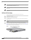
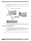
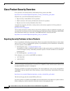
Step 3 Slide the open end of the ground lug over the exposed area of the wire.
Step 4 Using a Panduit crimping tool, crimp the ground lug to the wire.
Figure 9 Crimping the Ground Lug
Insulation
Wire lead
0.5 in. (12.7 mm)
±
0.02 in. (0.5 mm)
60528
200044