


36 4021203 Rev B
Front Panel LED Status Indicator Functions
Front Panel LED Status Indicator Functions
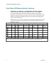
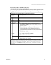
Initial Power Up, Calibration, and Registration (AC Power applied)
The following chart illustrates the sequence of steps and the corresponding
appearance of the cable modem front panel LED status indicators during power up,
calibration, and registration on the network when AC power is applied to the cable
modem. Use this chart to troubleshoot the power up, calibration, and registration
process of your cable modem.
Note: After the cable modem completes Step 7 (Registration Completed), the modem
proceeds immediately to Normal Operations. See Normal Operations (AC Power
Applied) (on page 37).
Front Panel LED Status Indicators During Initial Power Up, Calibration, and Registration
Step
1
2
3
4
5
6
7
8
Front Panel
Indicator
Power
Up
Self
Test
Downstream
Scan
Downstream
Signal Lock
Ranging
Requesting IP
Address
Registering
Registration
Completed
1
POWER
On
On
On
On
On
On
On
On
2
DS
Blinking
On
Blinking
On
On
On
On
On
3
US
Blinking
On
Off
Off
Blinking
On
On
On
4
ONLINE
Blinking
On
Off
Off
Off
Off
Blinking
On
5
LINK
Off
On
On or
Blinking
On or
Blinking
On or
Blinking
On or
Blinking
On or
Blinking
On or
Blinking
6
TEL1
Off
On
Off
Off
Off
Off
Off
Off
TEL2
Off
On
Off
Off
Off
Off
Off
Off
* The ONLINE LED illuminates continuously whenever a PC is connected to the modem, and it blinks to indicate that data is being
transferred. If the modem is used to provide telephone service only and is not connected to a PC, the ONLINE LED is off.