


3
Installation Note for Fan Tray Assemblies in Catalyst 4500 Series Switches
78-15335-01
Removing and Replacing the Chassis Fan Assembly
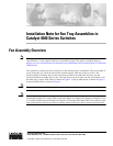
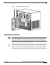
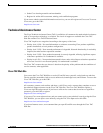
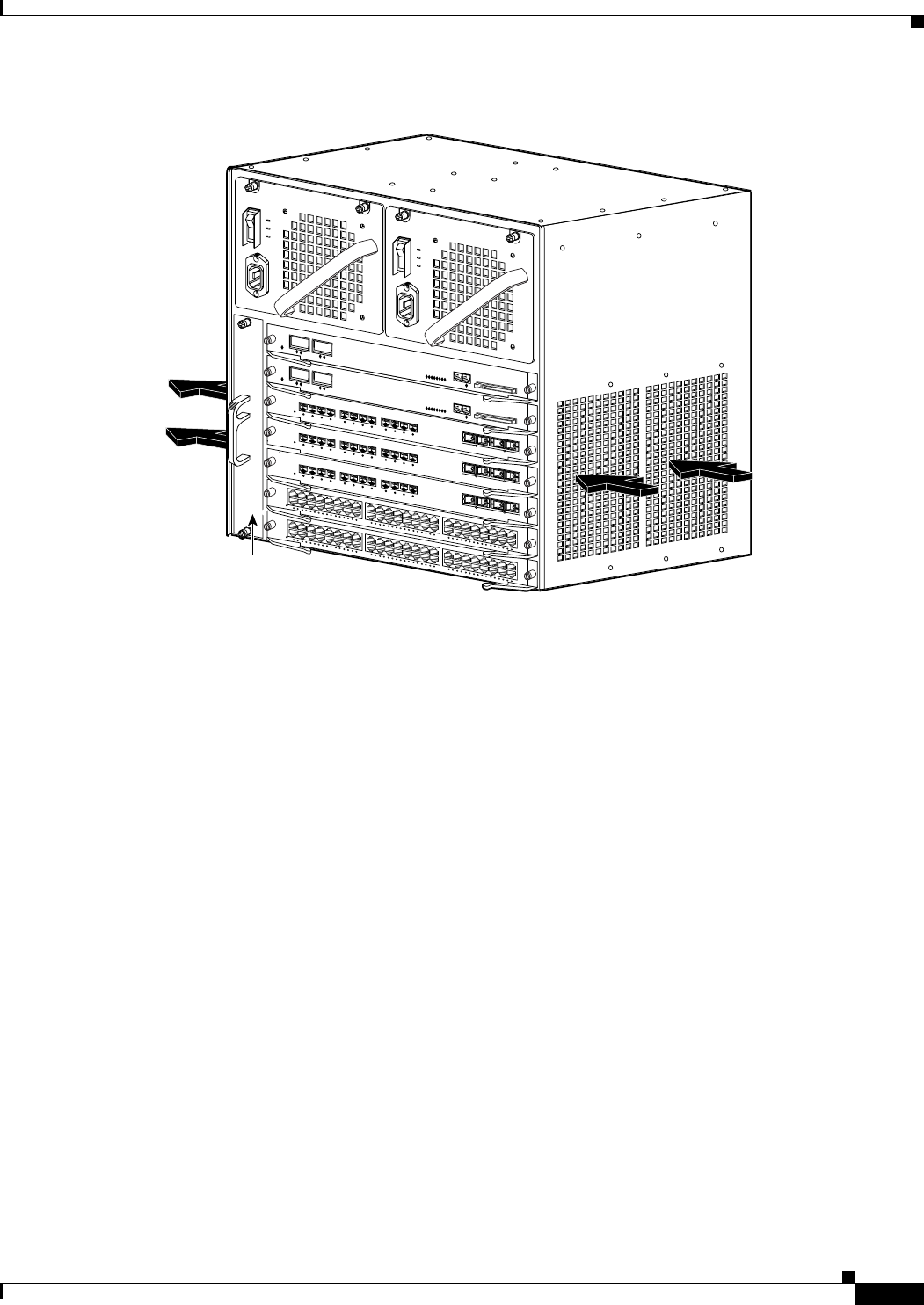
Figure 3 Catalyst 4507R Airflow
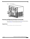
Removing and Replacing the Chassis Fan Assembly
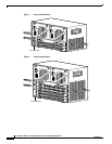
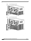
This section describes how to remove and install the chassis fan assembly for the Catalyst 4500 series
switches. See Figure 4 for the Catalyst 4503 system fan assembly, Figure 5 for the Catalyst 4506 system
fan assembly, and Figure 6 for the Catalyst 4507R system fan assemblies.
Required Tools
You will need a Phillips screwdriver for the following two procedures.
68111
Fan assembly
WS-X4448-GB-RJ45
STATUS
1
2
1
1
1
0
9
8
7
6
5
4
3
2
1
1
4
1
3
1
6
1
5
2
8
2
7
2
6
2
5
2
4
2
3
2
2
2
1
2
0
1
9
1
8
1
7
3
0
2
9
3
2
3
1
4
4
4
3
4
2
4
1
4
0
3
9
3
8
3
7
3
6
3
5
3
4
3
3
4
6
4
5
4
8
4
7
1
0
/
1
0
0
B
A
S
E
-
T
X
E
T
H
E
R
N
E
T
M
U
L
T
I
-
S
P
E
E
D
G
I
G
A
B
I
T
E
T
H
E
R
N
E
T
S
W
I
T
C
H
I
N
G
M
O
D
U
L
E
WS-X4448-GB-RJ45
STATUS
1
2
1
1
1
0
9
8
7
6
5
4
3
2
1
1
4
1
3
1
6
1
5
2
8
2
7
2
6
2
5
2
4
2
3
2
2
2
1
2
0
1
9
1
8
1
7
3
0
2
9
3
2
3
1
4
4
4
3
4
2
4
1
4
0
3
9
3
8
3
7
3
6
3
5
3
4
3
3
4
6
4
5
4
8
4
7
1
0
/
1
0
0
B
A
S
E
-
T
X
E
T
H
E
R
N
E
T
M
U
L
T
I
-
S
P
E
E
D
G
I
G
A
B
I
T
E
T
H
E
R
N
E
T
S
W
I
T
C
H
IN
G
M
O
D
U
L
E
1
S
T
A
T
U
S
W
S
-X
4
41
2
-2
G
B
-T
X
2
3
4
5
6
7
8
9
1
0
11
1
2
1
7
1
S
T
A
T
U
S
W
S
-X
4
4
12
-2G
B
-T
X
2
3
4
5
6
7
8
9
1
0
1
1
1
2
1
7
1
S
T
A
TU
S
W
S
-X
4
41
2
-2G
B-
T
X
2
3
4
5
6
7
8
9
1
0
1
1
1
2
17
U
P
L
IN
K
UP
LIN
K
CONSOLE
10/100
BASE-TX
STATUS
UP
L
IN
K
U
P
LIN
K
C
ONS
O
LE
10/100
BAS
E-TX
STATUS