


1-3
Cisco Wide Area Virtualization Engine 274 and 474 Hardware Installation Guide
OL-17739-01
Chapter 1 Introducing the Cisco Wide Area Virtualization Engine
Hardware Features
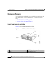
The power control button powers up and powers down the system.
Note Any USB connector can be used to connect a keyboard, and the video connector
can be used to connect a monitor. The keyboard and monitor are used only during
the BIOS boot process for troubleshooting purposes. After the BIOS boots, all
input and output for the appliance is by way of the serial console port.
Table 1-1 describes the front panel LEDs and their functions.
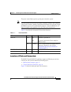
Location of Ports and Connectors
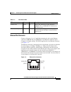
The WAVE-274 and WAVE-474 appliances support one Ethernet port and one
console port. This section contains the following topics:
• Ethernet Port Connector, page 1-5
• Console Port Serial Connector, page 1-6
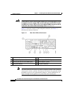
Figure 1-2 shows the back panel ports and connectors.
Ta b l e 1-1 Front Panel LEDs
LED Color State Description
Power-on Green On
Off
Appliance is powered on.
AC power is not present. Power supply or
LED has failed.
Red Flashing There is a problem with the computer and it is
displaying a diagnostic code. See the
“Troubleshooting the System Hardware”
section on page 5-1.
Hard disk drive activity Green Flashing Hard disk drive is in use.
DVD-ROM drive activity Green On CD/DVD drive is in use.