


4-3
Catalyst 4948E and Catalyst 4948E-F Switch Installation Guide
OL-21561-02
Chapter 4 Removal and Replacement Procedures
Removing and Installing the DC-Input Power Supply
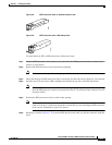
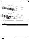
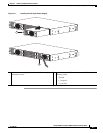
Step 3 Disconnect the DC-input cables from the power supply terminal block in this order (See Figure 4-1, top
view):
1. Positive (+) source DC cable from the positive (+) terminal
2. Negative (–) source DC cable from the negative (–) terminal
3. Ground cable from the ground terminal
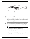
Step 4 Loosen the captive installation screw on the power supply.
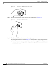
Step 5 Grasp the power supply handle with one hand, and slide the power supply halfway out of the chassis.
Place your other hand underneath the power supply, as shown in
Figure 4-1 (bottom view), and slide the
power supply completely out of the chassis. Set the power supply aside.
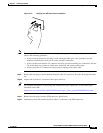
Note The DC power supply is equipped with an EMI gasket on the top and bottom (on the front edge)
of the power supply. When sliding the power supply into or out of the power supply bay, be
careful not to damage the EMI gaskets.
Step 6 If the power supply bay is to remain empty, install a blank faceplate (WS-X4994) over the opening, and
secure it in place with the captive installation screw.