


2-2
Installation and Upgrade Guide for Cisco Unified Videoconferencing 3545 PRI Gateway and 3545 Serial Gateway Release 5.5
OL-14912-01
Chapter 2 Installing the Cisco Unified Videoconferencing 3545 Gateway
Physical Description
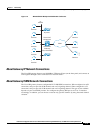
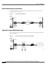
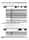
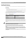
Figure 2-1 Gateway Front Panel
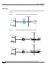
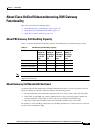
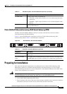
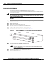
Cisco Unified Videoconferencing 3545 PRI Gateway RTM
The Rear Transition Module (RTM) provides the PRI line connections for the Cisco Unified
Videoconferencing 3545 PRI Gateway.
Figure 2-2 shows the RTM panel components of the Cisco Unified Videoconferencing 3545
PRI Gateway module. Table 2-2 describes these components.
Figure 2-2 PRI Gateway: Rear Transition Module
Table 2-1 Front Panel Components
Component Description
10/100 Base T-1
connector
An RJ-45 connector that provides the primary Ethernet connection for the IP
network port.
SERIAL connector A DB-9 connector that allows you to connect a PC terminal for local
configuration.
RST button Allows you to reset the gateway manually.
GK Reg LED Lights green when the gateway is registered with a gatekeeper.
CD LED Lights green when at least one gateway port connection is online.
ACT LED Lights green to indicate that there are active calls in the gateway.
ALARM LED Lights green to indicate that an error has occurred and the gateway requires
resetting.
10/100 Base T-1 LEDs The top part of the 10/100 Base T-1 connector contains two LED indicators.
The left-hand LED lights green when the local IP network link is active. The
right-hand LED lights green if the connection speed is 100 Mbps, and is off
when the connection speed is 10 Mbps.
SWAP RDY LED Hot Swap indication. Lights blue when the latches of a board are unlocked
and it is safe to remove the board from the chassis. Goes off when the board
is completely detached.
157269
10/100Base T-1
SERIAL
RST
ACTALARM
CDGK Reg
SWAP
RDY
Table 2-2 PRI Gateway Rear Transition Module Components
Component Description
ACT LEDs Lights green to indicate that there are active calls in the gateway.
D-Ch LEDs Lights green to indicate that the PRI line is enabled and a carrier signal is
detected.
157272
PORT-1PORT-2
ACT
D-Ch
ALARM
ACT
D-Ch
ALARM