


2-11
Cisco 806 Router Hardware Installation Guide
78-10432-01
Chapter 2 Installation
Installing Your Router
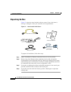
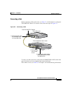
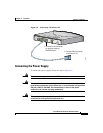
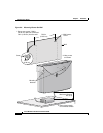
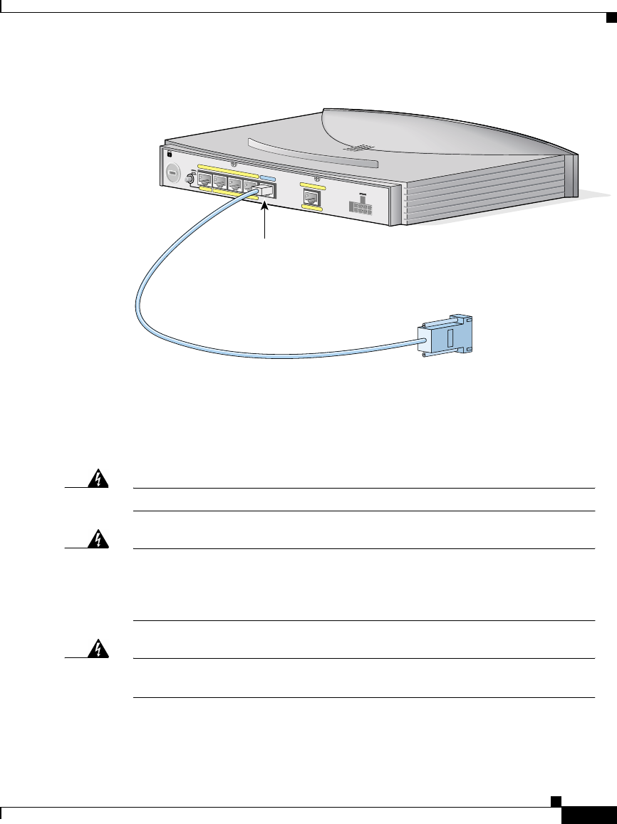
Figure 2-6 Connecting a Terminal or PC
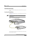
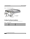
Connecting the Power Supply
To connect the power supply, follow the steps in Figure 2-7.
Warning
The device is designed to work with TN power systems.
Warning
This product relies on the building’s installation for short-circuit
(overcurrent) protection. Ensure that a fuse or circuit breaker no larger than
120 VAC, 15A U.S. (240 VAC, 16A international) is used on the phase
conductors (all current-carrying conductors).
Warning
This equipment is designed to be grounded. Ensure that the host is
connected to earth ground during normal use.
ETHERNET
TO HUB
TO PC
+5 VDC
4
32
1
10BASET
M
odel Cisco 806
COMPUTERS (E0)
ETHERNET 10BASET
INTERNET (E1)
CONSOLE
2. Connect DB-9 connector
to terminal or PC.
1. Connect RJ-45 connector
on light blue cable to
CONSOLE port.
51821