


Chapter 1 Cisco 850 Series and Cisco 870 Series Access Routers Cabling and Setup Quick Start Guide
Connect the Router
1-18
Cisco 850 Series and Cisco 870 Series Access Routers Cabling and Setup Quick Start Guide
78-16262-04
Follow the instructions provided with your broadband modem to determine which
port on the modem to connect to. Turn on the broadband modem if it is not already
turned on.
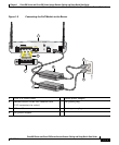
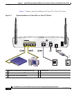
Step 7 Cisco 871 router only: Connect supported USB devices such as flash memory
modules or eTokens to the two USB ports. For more information, see the
Cisco Access Router USB Flash Module and USB eToken Hardware Installation
Guide. Proceed to Step 12.
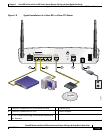
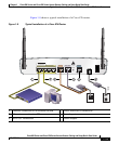
Step 8 Cisco 857 and Cisco 877 routers only: Connect the ADSLoPOTS port on the
router to the telephone wall jack by using the lavender DSL cable. If the ADSL
line is also used for voice communication, you can prevent disruption to data
communication by connecting the router to an ADSL splitter, or by installing
microfilters between telephones or fax equipment and the wall jack. Proceed to
Step 12.
Caution Both LAN and WAN ports can use RJ-45 connectors. Use caution when
connecting cables to these connectors. To avoid damage to the router, do not
connect telephone-network voltage (TNV) circuits (such as ISDN or DSL
circuits) to safety extra-low voltage (SELV) circuits (such as LAN circuits).
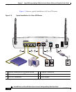
Step 9 Cisco 876 and Cisco 878 routers only: For dial backup and remote management,
you can connect the ISDN S/T port to a Network Termination (NT1) box or an
ADSL splitter, using the orange ISDN S/T cable (ordered separately). Continue
to Step 10 or proceed to Step 11, as appropriate for your router model.
Step 10 Cisco 876 routers only: Connect the DSL cable to the ADSLoISDN port on the
router and to the ADSL splitter or wall socket. If you are using an ADSL splitter,
connect the splitter to the wall socket using a Category 5 unshielded twisted-pair
cable. Proceed to Step 12.
Step 11 Cisco 878 routers only: Connect the DSL cable to the G.SHDSL port on the router
and to the wall socket.
Step 12 All router models: Connect power to the router, and turn on the router. Be sure to
use the power supply that was shipped with the router. Other power supplies will
not connect to the router.
The green OK LED on the front panel of the router lights up when you connect
the router to a power source. The router is now ready for use.
If the green OK LED does not turn on, see the “Troubleshooting” chapter in the
Cisco 850 Series and Cisco 870 Series Routers Hardware Installation Guide.