


4-14
Layer 3 Switching Software Feature and Configuration Guide
78-6235-04, Cisco IOS Release 12.0(10)W5(18)
Chapter 4 Configuring Interfaces
Configuring the POS OC-12c Uplink Interface (Catalyst 8540)
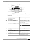
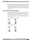
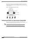
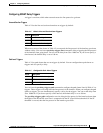
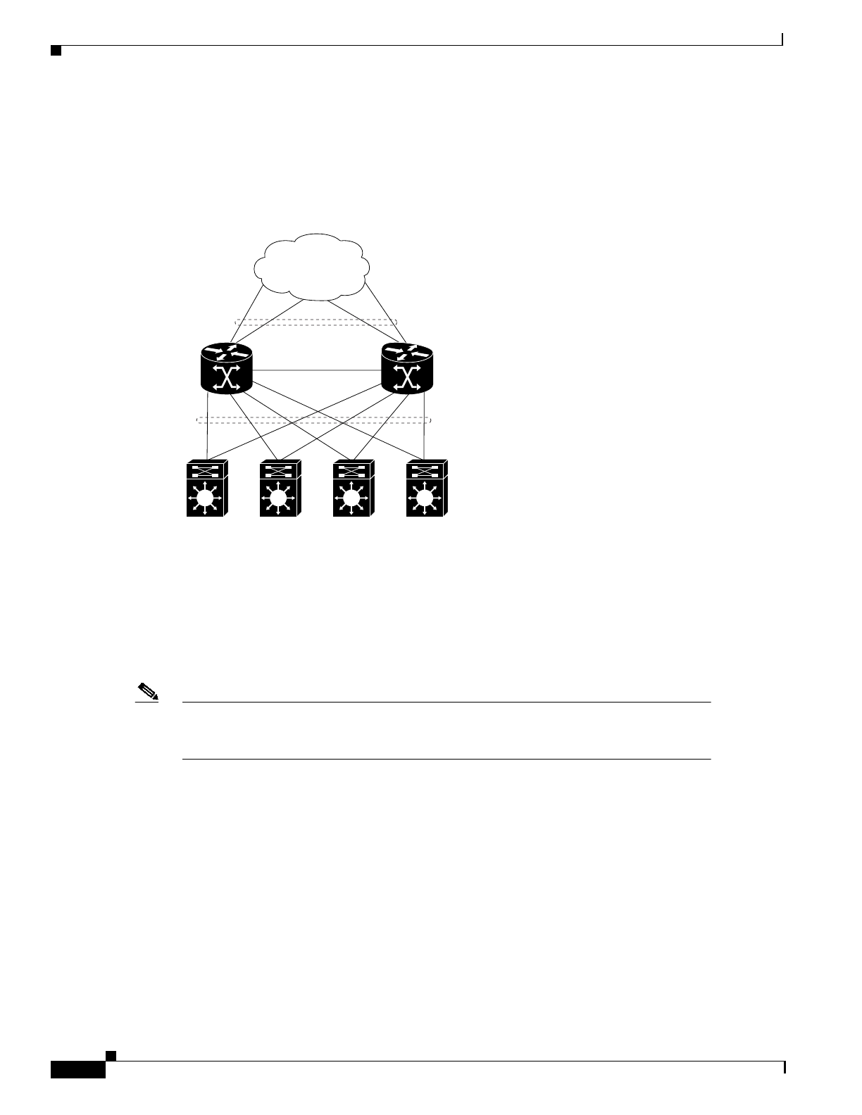
Figure 4-5 shows an example of a service provider application of the POS OC-12c uplink interface
module. Here traffic is aggregated from Catalyst 8500 CSRs over POS OC-12c interfaces to Cisco
12000 GSRs. POS OC-48 interfaces on the Cisco 12000 gigabit switch routers then provide the uplinks
to the Internet backbone.
Figure 4-5 POS for Aggregated Traffic Uplink to Internet
Configuring the POS OC-12c UplinkInterface (Catalyst 8540)
This section describes the default configuration of the POS OC-12c uplink interface, initial
configurations you should perform for a newly installed interface, and optional configurations you can
do to customize the interfaces to the requirements of your network.
Note The POS OC-12c uplink interface module consists of one OC-12c port and one enhanced
Gigabit Ethernet port. For instructions on configuring the Gigabit Ethernet interface, see
the “About the Enhanced Gigabit Ethernet Interfaces (Catalyst 8540)” section on page 4-5.
Internet
Backbone
OC-48c/STM-16
OC-12c/STM-4 POS
OC-12c/STM-4 POS
Cisco 12000 GSRs
Catalyst 8540s
30747