


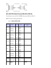

EIA−530 DTE Cable Pinouts (DB−60 to DB−25)
The table below shows the EIA−530 DTE cable pinouts (DB−60 to DB−25).
Note: The arrows indicate signal direction:
−−−> indicates DTE to DCE•
<−−− indicates DCE to DTE•
60 Pin
1
Signal 25 Pin Signal
Direction DTE
DCE
2
J1−11
J1−12
TxD/RxD+
TxD/RxD−
J2−2
J2−14
BA(A),
TxD+
BA(B),
TxD−
−−−>
−−−>
J1−28
J1−27
RxD/TxD+
RxD/TxD−
J2−3
J2−16
BA(A),
RxD+
BB(B),
RxD−
<−−−
<−−−
J1−9
J1−10
RTS/CTS+
RTS/CTS−
J2−4
J2−19
CA(A),
RTS+
CA(B),
RTS−
−−−>
−−−>
J1−1
J1−2
CTS/RTS+
CTS/RTS−
J2−5
J2−13
CB(A),
CTS+
CB(B),
CTS−
<−−−
<−−−
J1−3
J1−4
DSR/DTR+
DSR/DTR−
J2−6
J2−22
CC(A),
DSR+
CC(B),
DSR−
<−−−
<−−−
J1−46
J1−47
Shield_GND
MODE_2
J2−1
−
Shield
−
Shorted
J1−48 GND − − Shorted