


11
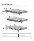
5 Rack-Mounting
This section covers basic 19-inch rack-mounting and switch port connections. As an example, all the
illustrations show the Catalyst 3560E-48 PoE switch. You can install and connect other
Catalyst 3560-E switches as shown in these illustrations. For additional installation and cabling
information, see the hardware installation guide on Cisco.com.
Equipment That You Supply
You need a Phillips screwdriver to rack-mount the switch.
Before You Begin
Before installing the switch, verify that these guidelines are met:
• Clearance to front and rear panels is such that
–
Front-panel indicators can be easily read.
–
Access to ports is sufficient for unrestricted cabling.
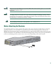
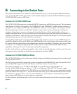
• For switches that support the RPS 2300, confirm that you have access to the switch rear panel to
connect the RPS 2300. If you do not have access to the rear panel, you should cable the switches
before you rack-mount them.
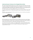
• For switches with the optional 1150-W power supply module (model C3K-PWR-1150WAC), first
rack-mount the switch before installing the power supply module.
• AC power cord can reach from the AC power outlet to the connector on the switch rear panel.
• Cabling is away from sources of electrical noise, such as radios, power lines, and fluorescent
lighting fixtures. Make sure the cabling is safely away from other devices that might damage the
cables.
• Airflow around the switch and through the vents is unrestricted.
• Temperature around the unit does not exceed 113°F (45°C). If the switch is installed in a closed
or multirack assembly, the temperature around it might be greater than normal room temperature.
• For copper connections on Ethernet ports, cable lengths from the switch to connected devices can
be up to 328 feet (100 meters).
• For cable lengths for X2 transceiver modules and SFP-module connections, see the hardware
installation guide on Cisco.com and the documentation that shipped with the module.