


1-11
Getting Started Guide for the Catalyst Express 500 Switches
OL-9340-01
Chapter 1 Getting Started Guide
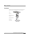
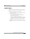
Install the Switch
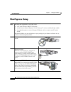
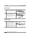
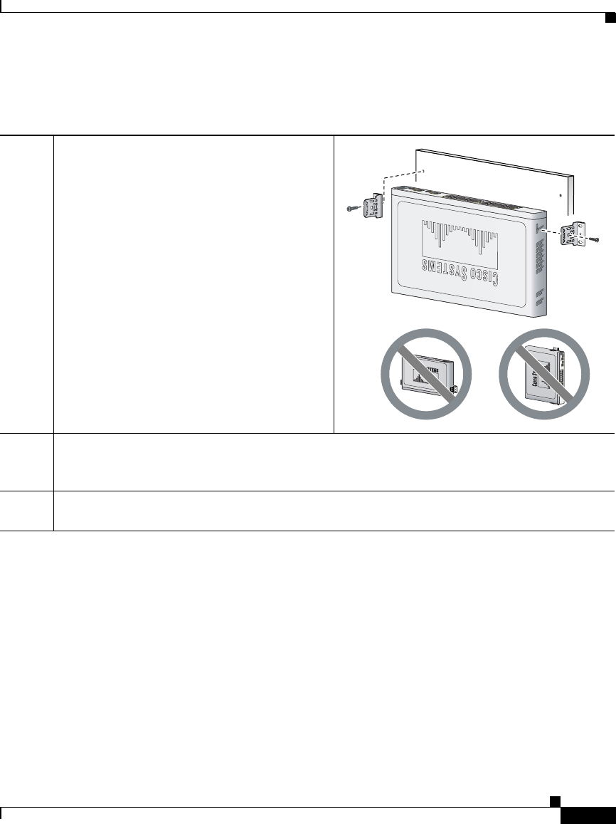
Wall-mounting
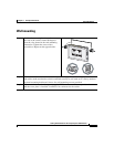
Step 1
Position the mounting bracket and screw on
the side of the switch, rotated 90-degrees
from the view shown in the rack-mounting
illustration. Tighten the screw with a
screwdriver. Repeat on the opposite side.
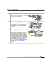
Step 2
Mount the switch on the wall with the front panel facing up. For the best support of the switch
and cables, make sure that the switch is attached securely to wall studs or to a firmly attached
plywood mounting backboard. Screws for wall-mounting are not provided.
Step 3
If your switch has a redundant power supply (RPS) connector on the rear panel, make sure
that the cover plate is installed if an RPS is not connected to the switch.
C
i
s
c
o
2
9
6
0
s
er
i
es
+
P
o
E
-
4
2
1
1
X
2X
P
O
W
E
R
OV
E
R
E
T
H
E
R
N
E
T
1
1X
12
X
4
3
6
5
8
7
1
0
9
1
2
1
1
1
4
1
3
1
3
X
14
X
23
X
2
4
X
16
15
1
8
17
2
0
1
9
22
2
1
2
4
23
25
2
5
2
6
2
6
Cisco 2960
series
+PoE-4
2
1
1X
2X
POWER
OVER
ETHERNET
11X
12X
4
3
6
5
8
7
10
9
12
11
14
13
13X
14X
23X
24X
16
15
18
17
20
19
22
21
24
23
25
25
26
26