


12
Cisco 40-Gigabit and 100-Gigabit CFP Transceiver Modules Installation Note
OL-23946-01
Required Tools
Warning
Ultimate disposal of this product should be handled according to all national laws and regulations.
Statement 1040
Warning
Use of controls, adjustments, or performing procedures other than those specified may result in
hazardous radiation exposure.
Statement 1057
Required Tools
You will need these tools to install the CFP transceiver module:
• Small flat-blade screwdriver for removing the CFP transceiver socket cover.
• Wrist strap or other personal grounding device to prevent electro-static discharge (ESD)
occurrences.
• Fiber-optic end-face cleaning tools and inspection equipment. For complete information on
inspecting and cleaning fiber-optic connections, refer to the white paper at this URL:
http://www.cisco.com/en/US/tech/tk482/tk876/technologies_white_paper09186a0080254eba.shtml
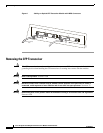
Installing the CFP Transceiver
Caution The CFP transceiver is a static-sensitive device. Always use an ESD wrist strap or similar individual
grounding device when handling the CFP transceivers or coming into contact with the modules.
To install a CFP transceiver, follow these steps:
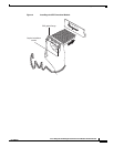
Step 1 Remove the CFP transceiver from its protective packaging.
Step 2 Check the label on the CFP transceiver body to verify that you have the correct model for your network.
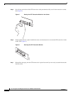
Step 3 Remove the dust plug from the CFP transceiver module optical port and set it aside.
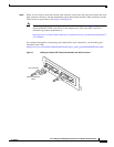
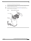
Step 4 Align the CFP device into the transceiver port socket of your networking module, and slide it in until the
CFP transceiver EMI gasket flange makes contact with the module faceplate. (See Figure 4.)