


2 Cisco 7000 and Cisco 7507 Chassis Replacement Instructions
Product Overview
Product Overview
The Cisco 7000 and Cisco 7507 replacement chassis comprise the sheet metal housing, front chassis
panels, and all internal components (MAS-7K and MAS-7507, respectively). An optional
replacement chassis is shipped with a spare power supply (CHAS-7K and CHAS-7507,
respectively).
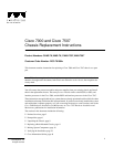
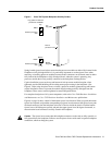
The rear of the chassis contains the seven processor slots and the two power supply bays. The
processor slots in the replacement chassis contain blank board carriers, which you will remove
individually as you install the interface processors from the old system. You will complete the
system by installing the processor modules and power supplies that you remove from your existing
system.
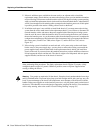
All of the components you will move to the new chassis are accessible from the rear of the chassis.
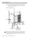
The descriptions that follow assume that you are viewing the chassis from the rear, or
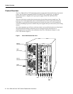
interface-processor end, which is the orientation of the Cisco 7000 shown in Figure 1 or the
Cisco 7507 shown in Figure 2.
Figure 1 Cisco 7000 Chassis Rear View
H2358
Slot 0
1
2
3 4 SP
or
SSP
slot
RP
slot
Upper
power supply
Lower
power supply
I
O
DC FAIL
AC POWER
I
O
DC FAIL
AC POWER
Captive
installation screw
Captive
installation screw