


REVIEW DRAFT—CISCO CONFIDENTIAL
1-4
Cisco 1805 DOCSIS Cable Router Hardware Installation Guide
OL-14661-01
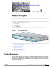
Chapter 1 Product Description
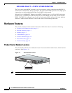
Hardware Features
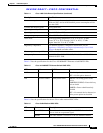
LED Indicators
Table 1-2 summarizes the LED indicators that are located in the router bezel or chassis, but not in the
interface cards installed in slot 0 or slot 1.
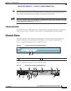
Chassis Ventilation
An internal three-speed fan provides chassis cooling. An onboard temperature sensor controls the fan
speed. The fan is always on when power is applied to the router. Under most conditions, the fan operates
at the slowest speed to conserve power and reduce fan noise. It operates at higher speeds when necessary
in conditions of higher ambient temperature.
Real-Time Clock
On system power up, an internal real-time clock with battery backup provides the system software with
time of day. This allows the system to verify the validity of a certification authority (CA) certificate. The
backup battery is a socketed lithium battery. This battery lasts the life of the router under the operating
environmental conditions specified for the router, and is not field replaceable.
Table 1-2 Summary of Cisco 1805 DOCSIS Cable Router LED Indicators
LED Color Description Location:
SYS PWR Green Router has successfully booted up and the software is functional.
This LED blinks while booting or in the ROM monitor.
Front
panel
SYS ACT Green Blinking when any packets are transmitted or received on any
WAN or LAN, or during monitoring system activity.
Front
panel
CF Green On when flash memory is busy. Do not remove the CompactFlash
memory card when this light is on.
Back
panel
FDX (FE 0/0) Green On indicates full-duplex operation. Off indicates half-duplex
operation.
Back
panel
100 (FE 0/0) Green On indicates a 100-Mbps link. Off indicates a 10-Mbps link. Back
panel
Link (FE 0/0) Green On when the router is correctly connected to a local Ethernet
LAN through Ethernet port 0.
Back
panel
FDX (FE 0/1) Green On indicates full-duplex operation. Off indicates half-duplex
operation.
Back
panel
100 (FE 0/1) Green On indicates a 100-Mbps link. Off indicates a 10-Mbps link. Back
panel
Link (FE 0/1) Green On when the router is correctly connected to a local Ethernet
LAN through Ethernet port 1.
Back
panel
AIM Green On indicates presence of an AIM in the internal AIM slot. Back
panel