


4 Cisco 7513 and Cisco 7576 Unpacking Instructions
Unpacking a Cisco 7513 or Cisco 7576
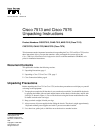
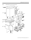
Step 7 Refer to Figure 3 and locate the small taped tube that contains the rack-mount kit packing.
Raise the top perimeter foam and remove the tube, with the rack-mount kit inside, and set
it aside.
Step 8 Remove the top perimeter foam and set it aside. (See Figure 3.)
Step 9 Remove the large taped tube and set it aside. Depending on your order, it should contain
the accessory box and up to two power supply boxes. Remove the accessory box first, and
then slide the large tube from the power supply boxes. After you expose the power supply
boxes, remove the power supplies and set them aside.
Step 10 Refer to Figure 3 and locate the two black board racks, located between the large taped
tube and the chassis. Remove the racks and set them aside.
Note The board racks provide a secure, safe place to temporarily store the processor modules when
you install the chassis in a rack. Refer to the Cisco 7500 Series Installation and Configuration Guide
for information on properly removing processor modules from the chassis.
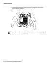
Caution The power supply boxes are heavy. Carefully remove them from the large taped tube.
Step 11 Carefully slide the bottom perimeter foam up and over the chassis. (Refer to Figure 3.)
Step 12 Using a nut driver, a phillips screwdriver, and a flat-blade screwdriver, locate and remove
the chassis anchors that fasten the chassis to the pallet. (Refer to Figure 3.) When these
anchors are removed, you can remove the chassis from the pallet.
Step 13 If present, remove the Flash memory card retainer, which is placed over the Route Switch
Processors (RSPs) installed in slots 6 or 7 in the chassis. (Refer to Figure 3.)
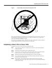
The chassis is now ready to be installed on a tabletop or in a rack. Although it is not required, we
recommend rack-mounting the chassis to assure optimum airflow, cable and maintenance
clearances, dust control, and accessibility.