


2-19
Cisco 831 Router and SOHO 91 Router Hardware Installation Guide
78-14784-02
Chapter 2 Installation
Mounting the Router
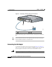
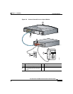
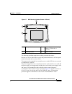
Figure 2-7 Wall-Mounting Brackets (Bottom of Router)
The following conditions must be met when you mount the router:
Because you will use the LEDs as status and problem indicators, the front panel
must face upward and be easily visible.
The router must be mounted low enough for you to see the LEDs in case you need
to troubleshoot a problem.
The power supply must rest on a horizontal surface such as the floor or a table. If
the power supply is not supported, it might place strain on the power supply cable
and cause it to disconnect from the connector on the router back panel.
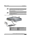
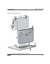
To mount the router, follow the steps given after Figure 2-8. Figure 2-9 shows a
Cisco 831 router, but it also applies to the SOHO 91 router. The mounting
procedure applies to both the Cisco 831 router and the SOHO 91 router.
80289
1
2
4
3
1 Front panel of router 3 Distance between two mounting
brackets (7 5/8 inches or
19.35 cm)
2 Mounting bracket 4 Bottom of router