


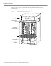
18 Fast Ethernet Interface Processor (FEIP) Installation and Configuration
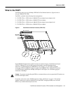
What Is the FEIP?
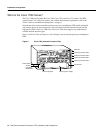
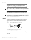
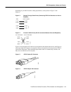
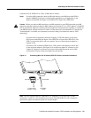
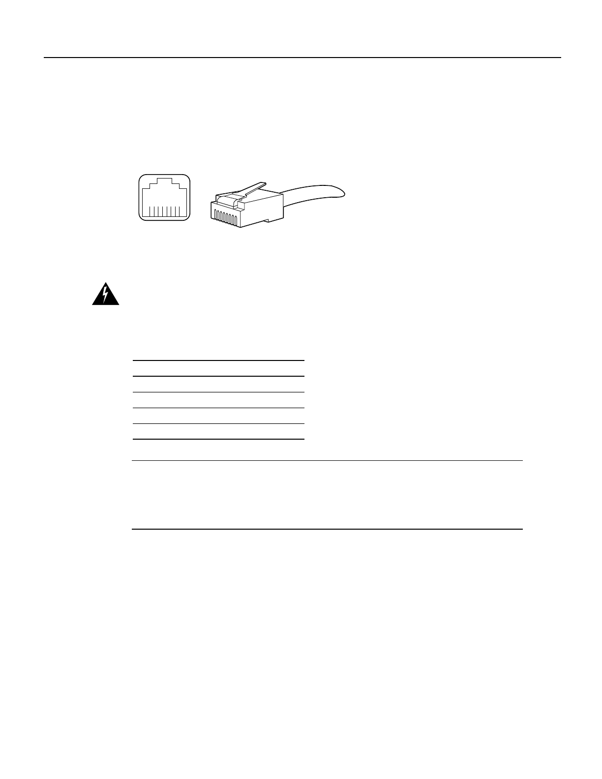
The RJ-45 connection does not require an external transceiver. The MII connection requires an
external physical sublayer (PHY) and an external transceiver. Figure 12 shows the RJ-45 cable
connectors. RJ-45 cables are not available from Cisco Systems, but are available from commercial
cable vendors. Table 2 lists the pinouts and signals for the RJ-45 connectors.
Figure 12 RJ-45 Connections (Connector and Plug)
Warning
The ports labeled “Ethernet,” “10BASE-T,” “Token Ring,” “Console,” and “AUX” are safety
extra-low voltage (SELV) circuits. SELV circuits should only be connected to other SELV circuits. Because
the BRI circuits are treated like telephone-network voltage, avoid connecting the SELV circuit to the
telephone network voltage (TNV) circuits.
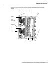
Table 2 RJ-45 Connector Pinout
Note Referring to the RJ-45 pinout in Table 2, proper common-mode line terminations should be
used for the unused Category 5, UTP cable pairs 4/5 and 7/8. Common-mode termination reduces
the contributions to electromagnetic interference (EMI) and susceptibility to common-mode
sources. Wire pairs 4/5 and 7/8 are actively terminated in the RJ-45, 100BASE-TX port circuitry in
the FEIP port adapter.
Pin Description
1 Receive Data + (RxD+)
2 RxD–
3 Transmit Data + (TxD+)
6 TxD–
H2936
8 7 6 5 4 3 2 1
RJ-45 connector