


4023034 Rev B 13
Back Panel Description
Back Panel Description
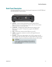
The following illustration describes the back panel components of the DPC3000 and
EPC3000 DOCSIS 3.0 cable modems.
1 REBOOT—Reset-to-Default Momentary Switch (Factory Reset)
Note: This button is for maintenance purposes only. Do not use unless
told to do so by your service provider.
2 ETHERNET—Bridged RJ-45 Gigabit Ethernet port connects to the
Ethernet port on your PC. This port also supports 10/100BASE-T
connections
3 USB—USB 2.0 port connects to the USB port on your PC
4 CABLE—F-Connector connects to an active cable signal from your
service provider
5 POWER—Connects the cable modem to the 12 VDC output of the AC
power adapter that is provided with your cable modem. Only use the AC
power adapter and power cord that is provided with your cable modem
CAUTION:
Avoid damage to your equipment. Only use the AC
power adapter and power cord that is provided with
your cable modem.